Wireless lighting and electrical device control system

a control system and electrical device technology, applied in the field of intelligent lighting control systems, can solve the problems of limiting the functionality and versatility of said systems, limiting the number of channels available for sensors and diagnostics and power management, and not having the ability to incorporate sensory input from items not related to lighting, so as to improve system integration and component reliability, save power, and increase security

Active Publication Date: 2014-12-25
PREMIER LIGHTING
View PDF2 Cites 99 Cited by
  • Summary
  • Abstract
  • Description
  • Claims
  • Application Information

AI Technical Summary

Benefits of technology

[0007]The Wireless Lighting and Electrical Device Control System is designed to provide an automated wireless independent lighting and electrical device control system which saves power, increases security, generates way finding information, and improves system integration and component reliability for a number of diverse functions. Independent control processing in each lighting fixture or electrical device allows a multiplicity of sensors to be locally employed and their data to control local conditions or communicate to adjoining fixtures and electrical devices and thereby control larger portions of the lighting system network or network to several unrelated systems.
[0008]The present invention enables a high level of system integration, versatility, and local control functionality. It provides diagnostic capability and allows for large sensor bandwidth. Wireless networking of sensor data can control illumination at each node, zone, level, or building, as well as communicate real-time status to its own or other local, nearby, online or remote system.

Problems solved by technology

A number of prior art systems incorporate automated lighting control functions based on input from ambient light or occupancy sensors or electronic timers, but their overall control system implementation does not offer sufficient scale of integrated control, sensor, power, security and lighting management functionality for complex infrastructures nor does it have the ability to incorporate sensory input from items not related to lighting.
This limits the functionality and versatility of said systems because the level of control is more centralized than specific to each independent light fixture.
Also the number of channels available for sensors and diagnostics and power management are necessarily limited when a single zone controller is the information bottleneck.
Another integration deficiency in simpler lighting control systems is the ability to control the level of illumination locally and specifically.
This general lack of local control limits the ability to manage power usage when an area is unoccupied or illuminated by daylight.
Dimming is also not well integrated with motion sensors on individual fixtures or devices to regulate or reduce power consumption when an area is vacant or unused for a length of time.
Other systems do not have an individual self-diagnostic capability or the added functionality of analyzing and reporting the power consumption of individual units or RF modules.
These systems are again controlled from the outside in, and are thereby limited in their versatility and scope.
No other lighting system has the ability to actually become a functioning part of a security or fire alarm system rather than simply reacting to signals from these systems.

Method used


Image

  • Wireless lighting and electrical device control system
  • Wireless lighting and electrical device control system
  • Wireless lighting and electrical device control system

Examples


Embodiment Construction

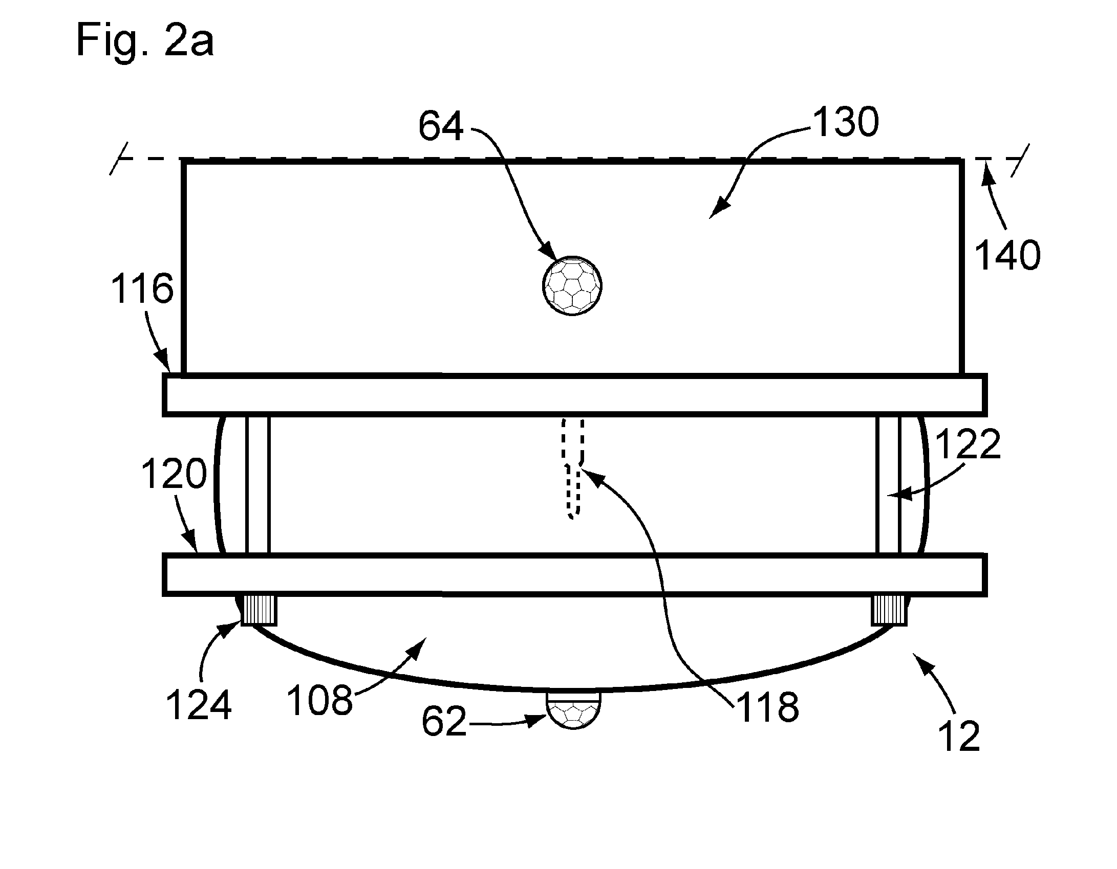
[0028]All relevant elements of the Wireless Lighting and Other Electrical Device Control System will now be introduced by reference to appended figures, and then how each element functions and interacts with each other element will be described herein.

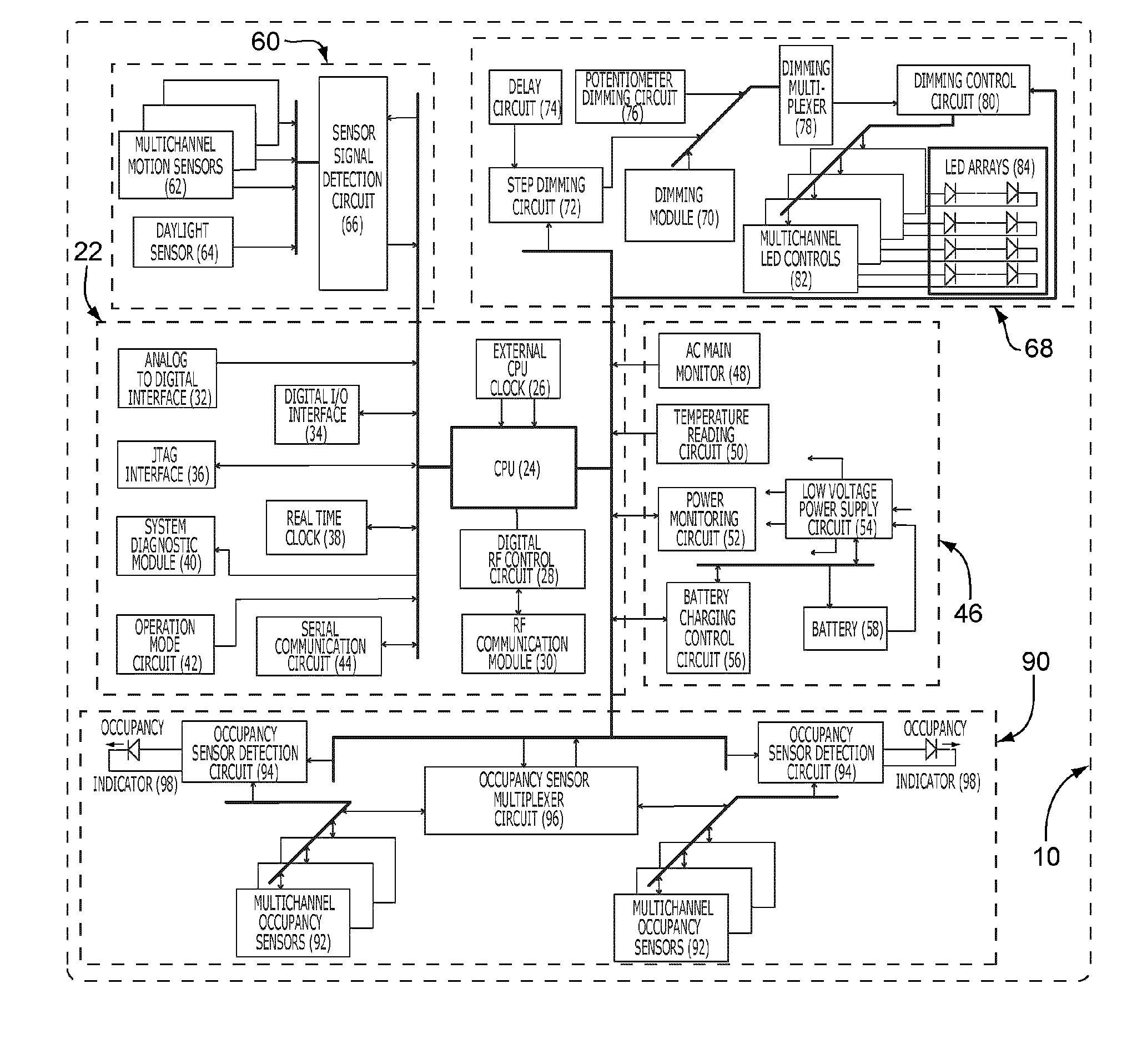
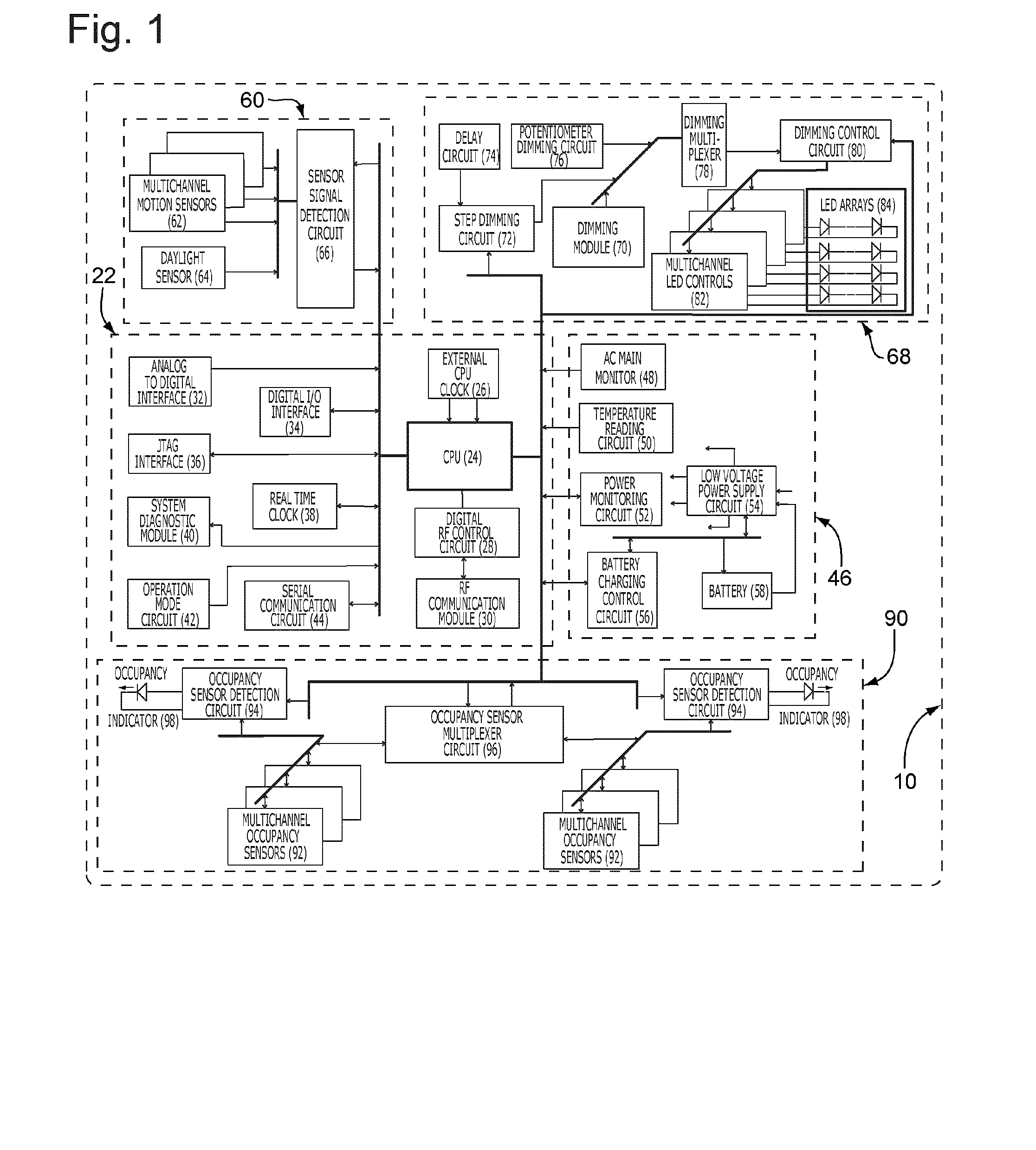
[0029]FIG. 1 is a representative block diagram illustrating interconnected sections of the Wireless Lighting and Electrical Device Control System 10 relating to control & networking 22, power management 46, motion / daylight sensing 60, dimming functions 68, and occupancy sensing 90. Elements of each section will now be listed and briefly described separately herein.

Control & Networking:

[0030]The core of control & networking 22 is the CPU 24, a programmable computer IC specifically designed to perform all lighting control and networking functions onboard each independent lighting fixture (12 or 14, see FIGS. 2a &3c). The CPU 24 requires an external CPU clock 26 for cycle timing and an accurately set real time clock 38 for record keeping....


PUM


Abstract

The invention provides a plurality of individually addressable radio frequency (RF) modules, any of which can be installed with any electrical device such as an ambient condition sensor or an ambient condition modifier. A prime example would be a light fixture, whether with or without a dimmable light source efficient dimming and integrated smart sensor networking related to the lighting system itself or to other systems such as parking monitors, fire alarm monitors or security alarm monitors. Independent control processing in each lighting fixture or electrical device allows a multiplicity of sensors to be locally employed and their data to control local conditions or communicate to adjoining fixtures and electrical devices and thereby control larger portions of the lighting system network or network to several unrelated systems.

Description

FIELD OF INVENTION[0001]This invention relates to a novel device in the general field of intelligent lighting control systems coupled with the ability to analyze from electronic sensors not related to lighting. More specifically, a wireless dimming smart sensor networking system deployable in any residential, commercial or industrial structure or streetscape. The electronic control of individual lighting fixtures via sensory input and radio frequency saves energy and extends lamp life and provides many other advantages due to greater system integration with sensor, diagnostic, power, emergency lighting and security systems. Housing an intelligent radio control module in a lighting fixture allows it to become a data gathering unit that can also analyze, react to and report input from other sensory devices not related to lighting such as but not limited to: occupancy sensors in parking garages that monitor the presence of vehicles in parking spaces, security sensors connected to a bui...

Claims


Application Information

Patent Timeline
Patent Type & Authority Applications(United States)
IPC IPC(8): H05B37/02H04L29/08
CPCH05B37/0272H05B37/0227H04W84/18H04L67/125H05B37/0218G08B13/19695G08B17/00G08G1/142G08G1/143G08G1/146H02J9/061H05B47/11H05B47/115H05B47/19Y02B20/40
Inventor HOLLAND, ANTHONYTOMA, ION
Owner PREMIER LIGHTING
Why Eureka
Try Eureka