Antenna Arrangement

a technology of antennas and pins, applied in the direction of simultaneous aerial operations, antenna earthing switch association, electric apparatus, etc., can solve the problems of mechanical instability of antennas, increased antennas, and antennas that are often not able to handle the demands of robustness, and achieve stable radio properties and lessen the impact of pins

Inactive Publication Date: 2014-12-25
PROANT
View PDF2 Cites 3 Cited by
  • Summary
  • Abstract
  • Description
  • Claims
  • Application Information

AI Technical Summary

Benefits of technology

[0015]In this way, an antenna arrangement is provided with an antenna element and an underlying printed circuit board with a ground plane, combined with the fact that the support pins of the antenna element can be placed at a distance from each other that allows for a stiff mechanical connection between the antenna element and the printed circuit board.
[0016]The combination of the antenna element with an underlying ground plane provides the anten

Problems solved by technology

Antennas for incorporation in radio equipment entails a plurality of demands that often are difficult to combine in one product.
If there is a ground plane below the antenna, the additional support pins 15 can not be used for mechanical support, for such a support then, only the pins for a radio signal and possibly ground, if desired, can be connected, Since these are placed near to ea

Method used


Image

  • Antenna Arrangement
  • Antenna Arrangement
  • Antenna Arrangement

Examples


Embodiment Construction

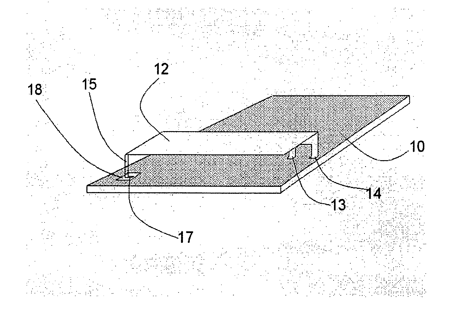
[0027]In order to create a robust antenna element that can be mounted on a printed circuit board, the antenna element shall be placed at a distance above the ground plane of the printed circuit board.

[0028]In order to be mechanically stable, at least two but In practice three or more pins to mount the antenna element with are needed.

[0029]In order to achieve an inexpensive product, it is most suitable that the antenna element and connection pins are formed in one and the same component, which most suitably is a piece of flat, electrically conductive material, which is solderable in a normal surface mounting process.

[0030]The process that in most cases is the least expensive to create a suitable design is to punch and bend a thin piece of sheet metal. The design is determined from the demands on resonance frequency, bandwidth and efficiency that the wireless system imposes.

[0031]An antenna element of the PIFA type shall also be placed at a suitable height above the ground plane to ha...


PUM


Abstract

The present invention provides a solution to how an antenna of the Patch or PIFA type can be made from a sheet metal in order for thereafter to be mounted on a printed circuit board with particularly formed mounting areas in order to provide both an inexpensive but yet robust and efficient antenna solution.

Description

TECHNICAL FIELD[0001]The present invention concerns an antenna arrangement comprising a printed circuit board and an antenna element mounted thereon.PRIOR ART AND BACKGROUND OF THE INVENTION[0002]Antennas for incorporation in radio equipment entails a plurality of demands that often are difficult to combine in one product. They should be robust and, at the same time, the one and the same antenna should be able to be used with several different products; they should be mountable in a normal surface mounting process and have a low cost.[0003]The antennas that usually are able to handle demands on robustness the best and can be used with a plurality of different products are antennas that are placed above a ground plane and are often called Patch or PIFA antennas (Planar Inverted F Antenna). These antennas need a point of connection to connect a radio signal to the antenna, however, in most cases two points of connection are used, one for a radio signal and another for the ground plane...

Claims


Application Information

Patent Timeline
IPC IPC(8): H01Q9/04H01Q5/00
CPCH01Q5/0027H01Q9/045H01Q1/243H01Q9/0421H01Q5/307H01Q5/357H01Q9/0407
Inventor RUTFORS, TOMAS
Owner PROANT
Why Eureka
Try Eureka