System for reducing return signal noise without radio frequency switching devices

Inactive Publication Date: 2014-12-25
ZILBERBERG DAVID
View PDF9 Cites 2 Cited by
  • Summary
  • Abstract
  • Description
  • Claims
  • Application Information

AI Technical Summary

Benefits of technology

The patent describes a device that reduces noise in signals transmitted through a cable television network. The device includes an amplifier and a noise checking circuit that filters signals from a device of a subscriber. When the signals are too weak, the device blocks them from being amplified, and when the signals are too strong, it supplies them to the amplifier. This device can be connected to a coaxial cable or installed outside of a subscriber's premises. It uses a low pass filter and a high pass filter to filter out noise from the signals. The device does not include any RF switches or relays. The technical effect is that the device improves the quality of signals transmitted through the cable television network.

Problems solved by technology

However, technical problems have reduced performances of such two-way networks.
In particular, interference of such two way network is an issue.
More particularly, interference due to ingress radio frequency (RF) noise has greatly affected the quality of the return path communication.
Ingress signals are particularly troublesome in the context of the return path communication because of the CATV two way network structural designs.
Several approaches know in the Art for signal noise reductions in electrical system are provided using RF electronic switch and RF relay, which has mainly drawbacks of generating high frequencies RF noise and longtime delay using a relay.

Method used


Image

  • System for reducing return signal noise without radio frequency switching devices
  • System for reducing return signal noise without radio frequency switching devices
  • System for reducing return signal noise without radio frequency switching devices

Examples


Embodiment Construction

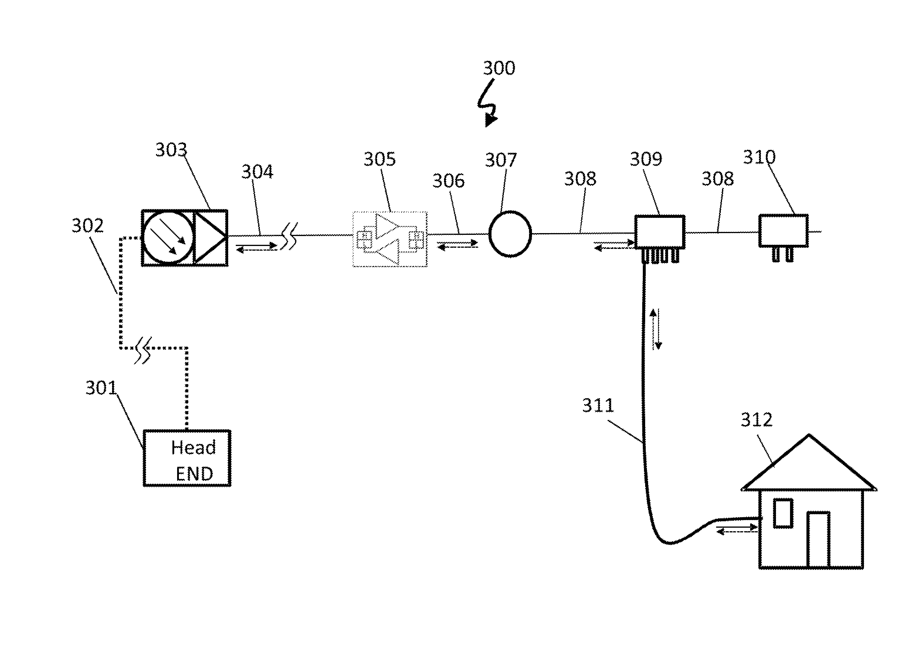
[0024]As mentioned earlier, comprehensive information networks are characterized as 2-way transmission systems having information flow to the head-ends via terminal interchanges and relays.

[0025]Transmission from head-end to terminal is “Forward” or “Downstream,” and transmission from terminal to head-end is “Return” or “Upstream”. A signal going downstream is a point-to-interface “broadcasting”, and is split; signals going upstream are interface-to-point converged. Either “broadcasting” or “converging” are conducted by splitters.

[0026]In the upstream path, upstream signals are combined with noise coming from various paths. Eventually, all noises are funneled to the head-end, the so called “Funnel Effect”. However, some of the noise components may have a high enough energy to mask the return signals, thus, may seriously affect the quality of the “Return” transmission.

[0027]Such noise components mostly come from terminals such as a cable modem where the commonly used amplifiers are o...


PUM


Abstract

A bi-directional return signal noise reducing unit includes first and second ports, an amplifier, and a noise checking circuit. The first port connects to a cable television network. The second port connects to one or more devices of a subscriber to the cable television network. The amplifier includes an input that is connected to the second port and includes an output that is connected to the first port. The noise checking circuit samples the signals flowing from the second port to the first port. The noise checking circuit also: when a level of the signals flowing from the second port toward the first port are less than a predetermined threshold, blocks the signals from the input of the amplifier; and when the level of the signals flowing from the second port toward the first port are greater than the predetermined threshold, supplies the signals to the input of the amplifier.

Description

CROSS-REFERENCE TO RELATED APPLICATIONS[0001]This application claims the benefit of and is a continuation-in-part of U.S. patent application Ser. No. 13 / 144,210 (now U.S. Pat. No. ______), filed Jul. 12, 2011; which is a 371 U.S. National Stage of International Application No. PCT / IL2010 / 000293, filed Apr. 6, 2010; which claims the benefit of U.S. Provisional Application No. 61 / 211,732, filed Apr. 1, 2009. The disclosures of the above applications are incorporated herein by reference.FIELD OF THE INVENTION[0002]The present invention relates to systems and methods for signal noise reduction in comprehensive information networks. More specifically, the present invention relates to a system for reducing return signal noise in a CATV (cable television) without the use of radio frequency (RF) switching devices and a method thereof.BACKGROUND OF THE INVENTION[0003]Cable modem technology is used in a widespread manner throughout the world. In general, the demand for CATV bandwidth and type...

Claims


Application Information

Patent Timeline
IPC IPC(8): H04N7/10H04N21/61
CPCH04N7/102H04N7/104H04N21/6168
Inventor ZILBERBERG, DAVID
Owner ZILBERBERG DAVID
Why Eureka
Try Eureka