Imaging apparatus and method of improving sensitivity of the same

a technology of imaging apparatus and sensitivity, which is applied in the field of imaging apparatus and a method of improving sensitivity, can solve the problems of variable noise generation, quality degradation, fixed pattern noise, etc., and achieve the effects of improving sensitivity, expanding the dynamic range of image signals, and preserving resolution

Inactive Publication Date: 2015-01-01
SAMSUNG ELECTRONICS CO LTD
View PDF9 Cites 0 Cited by
  • Summary
  • Abstract
  • Description
  • Claims
  • Application Information

AI Technical Summary

Benefits of technology

[0010]The present invention provides an imaging apparatus, which can preserve resolution and can also expand the dynamic range of an image signal under low illumination conditions by increasing the power of an output image signal in comparison to the power of noise, and a method of improving the sensitivity of the imaging apparatus.
[0011]The present invention also provides an imaging apparatus, which can improve sensitivity by preventing noise boost-up, and a method of improving the sensitivity of the imaging apparatus.
[0024]According to another aspect of the present invention, there is provided a method of improving the sensitivity of an imaging apparatus, the method comprising: pixel binning input image data to a given pixel size; determining a pixel binning gain based on the input data or the brightness of the input image data; and calculating output image data based on the pixel binned input image data and the pixel binning gain.
[0025]According to another aspect of the present invention, there is provided a method of improving the sensitivity of an imaging apparatus, the method comprising: pixel binning input image data to a given pixel size; filtering high frequency components in a plurality of directions of the input image data; determining a resolution preserving factor based on the high frequency components; and calculating output image data based on the pixel binned input image data, the high frequency components, and the resolution preserving factor.

Problems solved by technology

However, various kinds of noise are generated when light is converted into an electric signal.
Such noise includes dark current noise, kTC noise, and fixed pattern noise.
Dark current noise, which is thermal noise proportional to the temperature, is a major factor in image quality degradation under low illumination conditions. kTC noise is generated by various switching pulses that are used to drive a CMOS or a CCD camera.
Fixed pattern noise results from non-uniformity caused by manufacturing variations between pixels in an imaging device, such as a CMOS or a CCD.
Such noise is added to charges which are photoelectrically converted and accumulated by the imaging device, thereby degrading image quality.
Under high illumination conditions with a great amount of light, since noise is relatively small compared to photoelectrically converted and accumulated charges, image quality degradation is negligible.
However, under low illumination conditions, fixed pattern noise, dark current noise, and kTC noise become greater than photoelectrically converted and accumulated charges.
However, the imaging device having the large pixel pitch is expensive and the size of the imaging device should be increased to provide the same resolution.

Method used


Image

  • Imaging apparatus and method of improving sensitivity of the same
  • Imaging apparatus and method of improving sensitivity of the same
  • Imaging apparatus and method of improving sensitivity of the same

Examples


Embodiment Construction

[0041]The present invention will now be described more fully with reference to the accompanying drawings, in which exemplary embodiments of the invention are shown.

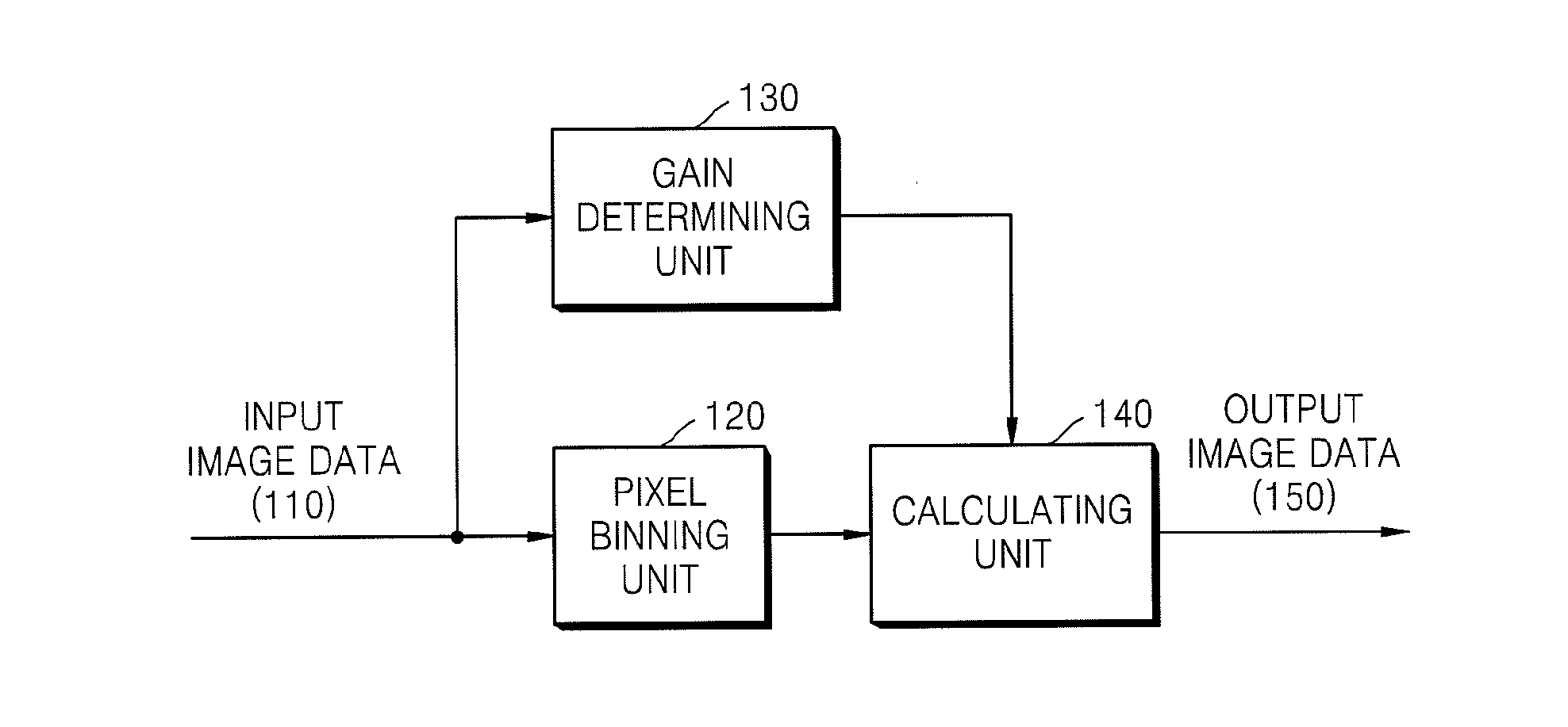
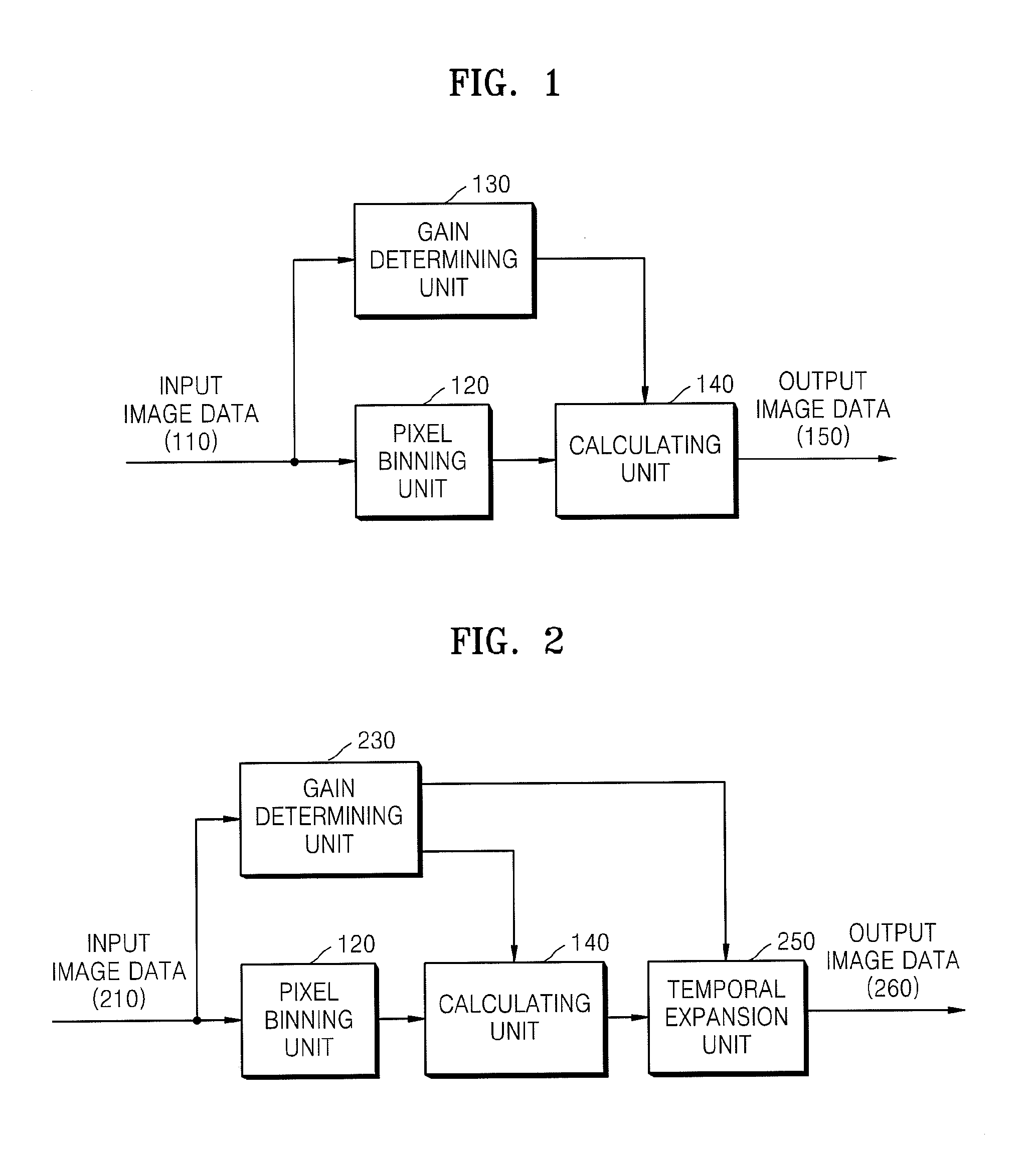
[0042]FIG. 1 is a block diagram of an imaging apparatus according to an exemplary embodiment of the present invention.

[0043]Referring to FIG. 1, the imaging apparatus includes a pixel binning unit 120, a gain determining unit 130, and a calculating unit 140.

[0044]The pixel binning unit 120 pixel bins input image data 110 to a predetermined pixel size, for example, 2×2 or 3×3. A plurality of pixel data adjacent to one pixel are combined into one pixel data. Since pixel binning is a process of combining data of a plurality of pixels into data of one pixel, sensitivity can be improved but resolution is reduced under low illumination conditions.

[0045]However, the pixel binning unit 120 of the imaging apparatus of FIG. 1 pixel bins the input image data 110 in a horizontal or vertical direction while preserving resolution of th...


PUM


Abstract

An imaging apparatus and a method improving the sensitivity of the imaging apparatus are provided. The imaging apparatus includes a pixel binning unit pixel binning input image data to a given pixel size; a gain determining unit determining a pixel binning gain based on the input image data or the brightness of the input image data; and a calculating unit calculating output image data based on the pixel binned input image data and the pixel binning gain. Accordingly, the resolution of input image data can be preserved and the dynamic range of an image signal under low illumination conditions can be expanded.

Description

CROSS-REFERENCE TO RELATED PATENT APPLICATION[0001]This is a divisional of U.S. patent application Ser. No. 12 / 020,597, filed Jan. 28, 2008, which claims priority from Korean Patent Application No. 10-2007-0069212, filed on Jul. 10, 2007, in the Korean Intellectual Property Office, the disclosure of which is incorporated herein in its entirety by reference.BACKGROUND OF THE INVENTION[0002]1. Field of the Invention[0003]Apparatus and methods consistent with the present invention relate to an imaging apparatus and a method of improving the sensitivity of the same, and more particularly, to an imaging apparatus, which can improve image data sensitivity under low illumination conditions and prevent noise, and a method of improving the sensitivity of the imaging apparatus.[0004]2. Description of the Related Art[0005]Imaging apparatuses, such as cameras or camcorders, convert light of an image into an electric signal, using an imaging device such as a complementary metal-oxide semiconduct...

Claims


Application Information

Patent Timeline
Patent Type & Authority Applications(United States)
IPC IPC(8): H04N5/347H04N5/361H04N5/335H04N5/351H04N5/355H04N5/243H04N5/363H04N5/357
CPCH04N5/357H04N5/355H04N5/347H04N5/243H04N23/76H04N25/46H04N25/57H04N5/57H04N25/60H04N1/409G06T5/003H04N5/208H04N5/142G06T2207/20182G06T2207/20192
Inventor KIM, IL-DOJUN, JAE-SUNGCHOI, BYUNG-SUN
Owner SAMSUNG ELECTRONICS CO LTD
Why Eureka
Try Eureka