Unlock instant, AI-driven research and patent intelligence for your innovation.

Liquid Applicator Device

Inactive Publication Date: 2015-01-01
IVM IP PTY LTD
View PDF29 Cites 6 Cited by
  • Summary
  • Abstract
  • Description
  • Claims
  • Application Information

AI Technical Summary

Benefits of technology

The invention provides a simple applicator device that can be used on plants. It is made up of a bladder, a hbox or housing, and a fluid coupling. The fluid coupling can connect to a conduit, which can have a hose barbed attachment. A retaining plate can hold the fluid coupling in place, and there is also a pouch to hold the conduit and make it easier to connect in use. Overall, this device makes it easier to apply fluids to plants.

Problems solved by technology

However it will be appreciated in regard to both U.S. Pat. Nos. 4,072,128 and 5,690,738 that these applicator devices would not be suitable for applying herbicides to plants as the substrate which is to be contacted by these applicator devices includes work pieces in the case of U.S. Pat. No. 5,690,738 and an internal surface of a tube in the case of U.S. Pat. No. 4,072,128.
It will also be appreciated that the structure of these applicator devices are relatively complicated.
Again the structure of this applicator is unnecessarily complicated having regard to the use of a upwardly canted backing plate.
Again this applicator would not be suitable for application to plants and is unnecessarily complicated and dangerous to users having regard to the feature of the hollow needle.
Again it is considered that the structure of this applicator head is unnecessarily complicated in that it requires a valve assembly which is dependant upon movement of the brush and consequent supply of liquid to the plants.
This applicator was also disadvantageous in that the required dose could not be properly calibrated.

Method used


Image

  • Liquid Applicator Device
  • Liquid Applicator Device
  • Liquid Applicator Device

Examples


first embodiment

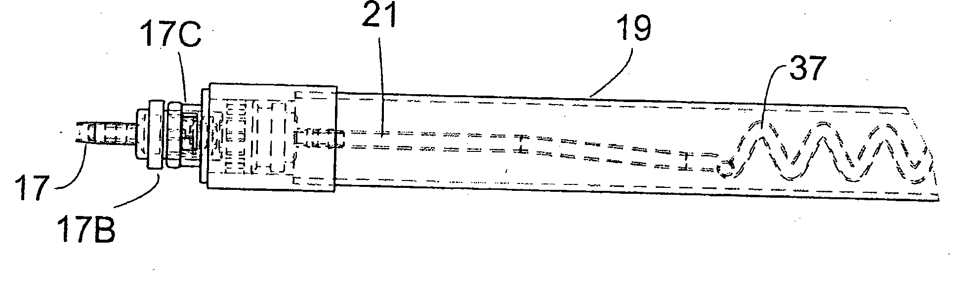
[0025]FIG. 1 is a side view of the applicator;

[0026]FIG. 1A is an enlarged view of detail “A” shown in FIG. 1;

[0027]FIG. 1B is an enlarged view of detail “B” shown in FIG. 1;

[0028]FIG. 1C is an enlarged view of detail “C” shown in FIG. 1;

[0029]FIG. 1D is an enlarged view of detail “D” shown in FIG. 1;

[0030]FIG. 1E is an enlarged view of detail “E” shown in FIG. 1;

[0031]FIG. 2 is a detailed side view of detail “E” shown in FIG. 1;

[0032]FIG. 3 is an exploded perspective of the applicator of FIG. 2;

[0033]FIG. 4 is a detailed side view of detail “D” shown in FIG. 1;

second embodiment

[0034]FIG. 5 is a perspective side view of the applicator of the invention;

[0035]FIG. 6 is an enlarged exploded perspective view of detail “F” shown in FIG. 5;

[0036]FIG. 7 is a perspective side view of detail “F” shown in FIG. 6;

third embodiment

[0037]FIG. 8 is a perspective view of the applicator of the invention;

[0038]FIG. 9 is an enlarged perspective view of detail “G” shown in FIG. 8;

[0039]FIG. 10 is an enlarged perspective view of detail “H” shown in FIG. 8;

[0040]FIG. 11 is an internal view or sectional view of the embodiment shown in FIG. 8;


PUM


Abstract

A liquid applicator (10, 10A, 10B, 10C, 10D, 10E, 10F) having (i) a container in the form of a collapsible bladder (11, 11A, 11B, 11C) for containing a supply of liquid in use; (ii) a positive displacement pump (12, 12A) in flow communication with the container (11, 11A, 11B, 11C) which has a variable capacity chamber for delivering a metered or measured quantity of liquid; and (Hi) a contact device (20, 46A, 46A, 60) in flow communication with the positive displacement pump (12, 12A) wherein the metered or measured dosage of liquid is delivered to a plant or other substrate.

Description

FIELD OF THE INVENTION[0001]This invention relates to an applicator device which may be utilised for selective delivery of fluids inclusive of liquids and gels to a desired substrate such as plants and other forms of vegetation and other substrates.BACKGROUND TO THE INVENTION[0002]Applicator devices are well known and reference may be made for example to U.S. Pat. No. 4,072,128 which comprises a body member of a liquid reservoir therein, a manually operable pump in communication with the reservoir and an applicator post mounted on the pump which may be connected to a hose. A metered amount of liquid is supplied to an inner surface of a portion of a tubular member by manually placing the tubular member portion over the applicator post and then pressing inwardly over the device.[0003]Reference also may be made to U.S. Pat. No. 5,690,738 which described a liquid dispenser and contact applicator having at least one roller for contacting advancing work pieces and applying liquid to surfa...

Claims


Application Information

Patent Timeline
IPC IPC(8): A01M21/04B05C17/005
CPCB05C17/00569A01M21/043B05C17/0052B05C17/00583A46B11/002A01M7/0085A01M7/0046
Inventor KAST, GEORGE
Owner IVM IP PTY LTD