Cover for male member

a cover and male technology, applied in the field of male members, can solve problems such as liquid leaking out of male luer's body

Active Publication Date: 2015-01-08
JMS CO LTD
View PDF8 Cites 49 Cited by
  • Summary
  • Abstract
  • Description
  • Claims
  • Application Information

AI Technical Summary

Benefits of technology

[0016]According to the present invention, portions that undergo almost no deformation and portions that undergo a large amount of bending deformation when subjected to compression force are formed so as to alternate in the circumferential direction of the compression units. Also, these two different types of portions substantially oppose each other in the central axis direction between adjacent compression units. This makes it possible to provide a cover for a male member that is not likely to undergo buckling deformation.

Problems solved by technology

However, since the male luer is exposed to the outside before being inserted into the needleless port and after being withdrawn, and there is a possibility of liquid leaking out from the male luer.

Method used


Image

  • Cover for male member
  • Cover for male member
  • Cover for male member

Examples


embodiment 1

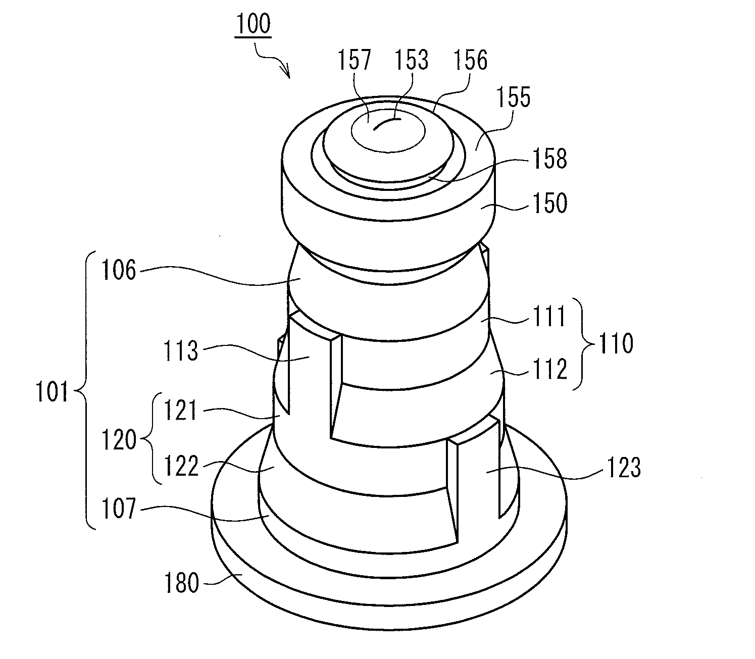
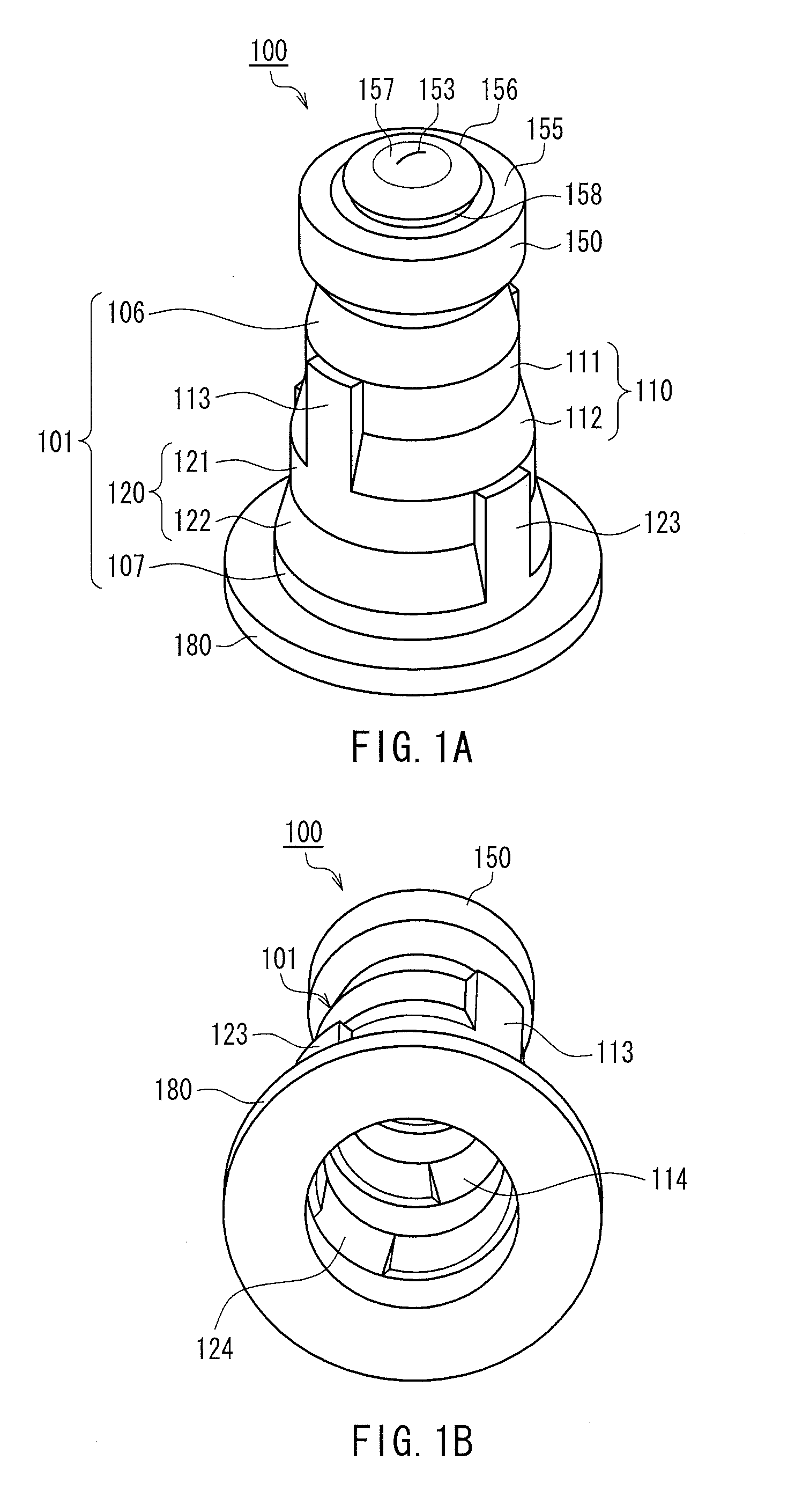
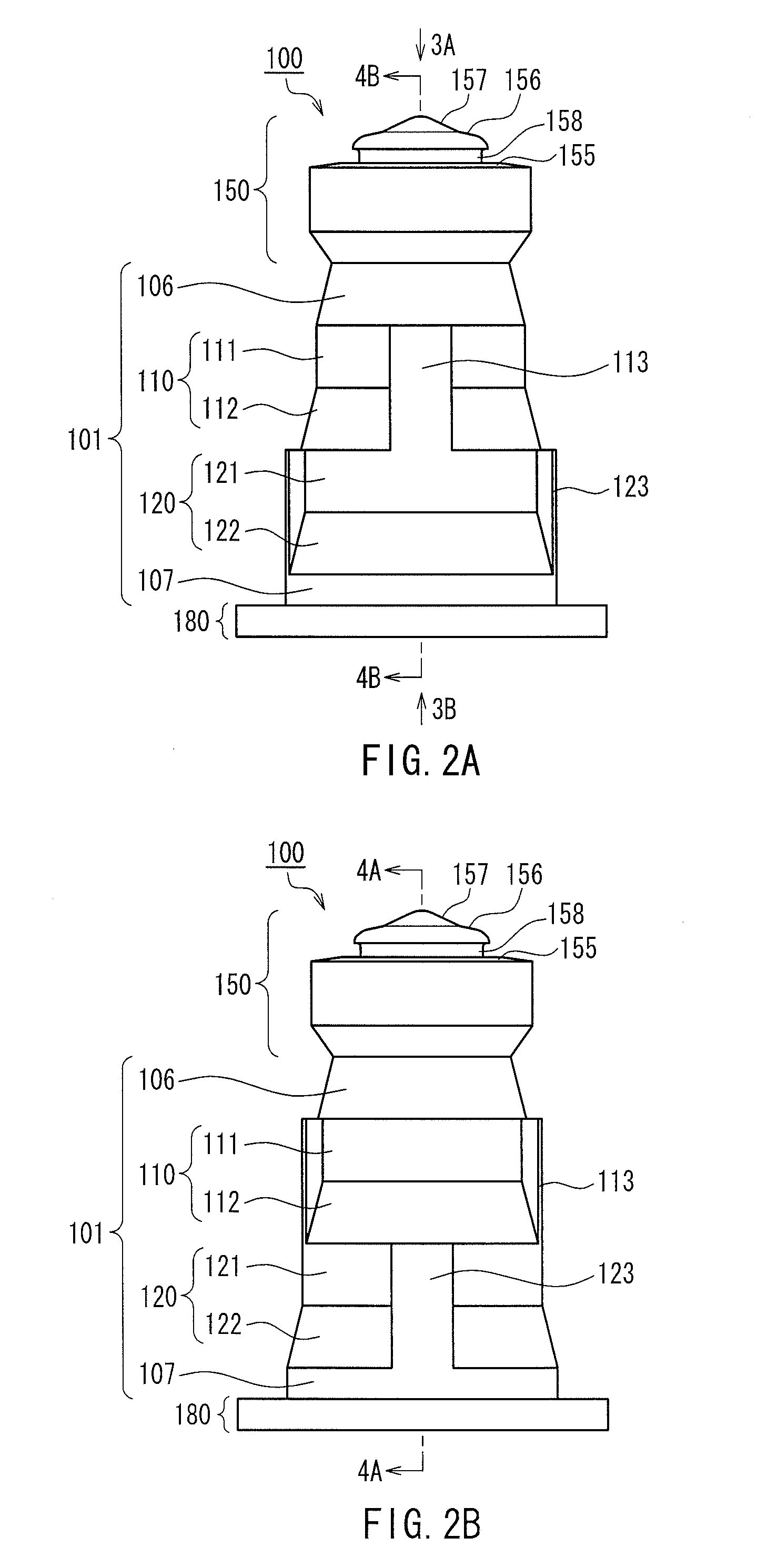
[0053]FIG. 1A is a perspective view of a cover for a male member (hereinafter referred to as simply a “cover”) 100 according to Embodiment 1 of the present invention as seen from above, and FIG. 1B is a perspective view of the cover 100 as seen from below. FIG. 2A is a front view of the cover 100, FIG. 2B is a side view of the cover 100, FIG. 3A is a plan view of the cover 100 as seen from an arrow 3A direction in FIG. 2A, and FIG. 3B is a bottom view of the cover 100 as seen from an arrow 3B direction in FIG. 2A. Furthermore, FIG. 4A is a cross-sectional view of the cover 100 taken along a plane including a line 4A-4A in FIG. 2B, and FIG. 4B is a cross-sectional view of the cover 100 taken along a plane including a line 4B-4B in FIG. 2A.

[0054]The cover 100 includes an outer circumferential wall 101 that has a substantially tubular shape, a head portion 150 provided at one end of the outer circumferential wall 101, and a ring-shaped base portion 180 provided at the other end of the ...

experiment 1

[0083]In Experiment 1, male luers 10 shown in FIG. 6 with the covers 100 and 500 attached were connected to the needleless port 950 (see FIG. 19). Aspects of the deformation of the covers 100 and 500 in the state before connection and the connected state were then observed by capturing cross-sectional images using X-ray CT.

[0084]FIGS. 8A and 8B are cross-sectional views showing the state before the male luer 10 having the cover 100 of Embodiment 1 attached thereto is connected to the needleless port 950. The cross-sections in FIGS. 8A and 8B are the same as the cross-sections in FIGS. 4A and 4B respectively.

[0085]FIGS. 9A and 9B are cross-sectional views showing the state where the male luer 10 having the cover 100 of Embodiment 1 attached thereto has been connected to the needleless port 950. The cross-sections in FIGS. 9A and 9B are the same as the cross-sections in FIGS. 8A and 8B respectively.

[0086]As shown in FIGS. 9A and 9B, the male luer 10 has passed through the slit 153 for...

experiment 2

[0096]Change in compressive load in the process of compressing the covers 100 and 500 used in Experiment 1 and then returning them (allowing them to extend) to their original state was measured.

[0097]FIG. 12 is a cross-sectional view for describing the method of Experiment 2 regarding the cover 100. Similarly to Experiment 1, the cover 100 was attached to a male luer 10. The base 15 of the male luer 10 was held such that the central axis 100a of the cover 100 was vertical. A compression block 50 provided with a hole 51 that can receive insertion of the male luer 10 was attached to an elevating apparatus (not shown) above the cover 100. As shown in FIG. 12, the position at which the edge of the opening of the hole 51 comes into contact with the head portion 150 of the cover 100 was set as the initial position of the compression block 50. The compression block 50 then was lowered from the initial position and thereafter raised to the initial position. The repulsive force applied to th...


PUM


Abstract

A head portion (150) is provided at one end of an outer circumferential wall (101) capable of elastic compression deformation. The outer circumferential wall includes multiple compression units (110, 120) that undergo deformation due to compression force in a central axis (100a) direction. Letting N be an integer of 2 or more, the compression units each have at least either N thick portions (113) or N thin portions (123) formed at equiangular intervals with respect to the central axis such that the thickness periodically changes in the circumferential direction. The phase with respect to the central axis of the periodic change in thickness is shifted between two compression units that are neighboring in the central axis direction.

Description

TECHNICAL FIELD[0001]The present invention relates to a cover for a male member that covers at least the tip of a bar-shaped male member in which a flow channel for flow of a liquid is formed.BACKGROUND ART[0002]When giving a patient an infusion or blood transfusion or performing extracorporeal blood circulation during surgery, it is necessary to form a channel (transport line) for transporting a liquid such as a drug solution or blood. Transport lines are generally formed by connecting containers, various types of instruments, tubes, and the like. One known method for connecting different members is the slip connection of a male luer serving as the male member and a needleless port serving as the female member (e.g., see Patent Documents 1 and 2). The needleless port has a partition wall member (hereinafter referred to as a “septum”) that is made of an elastic material such as rubber and has a linear slit (incision) formed in the central portion. The needleless port and the male lu...

Claims


Application Information

Patent Timeline
Patent Type & Authority Applications(United States)
IPC IPC(8): A61M39/02F16L55/10F16L37/30A61M39/26A61M39/04
CPCA61M39/02A61M39/26A61M39/045A61M2039/267F16L55/10A61M2039/263F16L37/30
Inventor TACHIZAKI, HITOSHI
Owner JMS CO LTD
Why Eureka
Try Eureka