Video signal transmitter apparatus and receiver apparatus using uncompressed transmission system of video signal

a video signal and receiver technology, applied in the field of video signal transmitter apparatus, video signal transmitting method, video signal receiver apparatus, video signal receiving method, can solve problems such as increase in circuit scale, and achieve the effect of lowering transmission rate and large increase in circuit scal

Active Publication Date: 2015-01-08
PANASONIC INTELLECTUAL PROPERTY MANAGEMENT CO LTD
View PDF3 Cites 9 Cited by
  • Summary
  • Abstract
  • Description
  • Claims
  • Application Information

AI Technical Summary

Benefits of technology

[0008]One non-limiting and exemplary embodiment provides a video signal transmitter apparatus, a video signal transmitting method, a video signal receiver appara...

Problems solved by technology

Due to this, there is such a problem that a large buffer m...

Method used


Image

  • Video signal transmitter apparatus and receiver apparatus using uncompressed transmission system of video signal
  • Video signal transmitter apparatus and receiver apparatus using uncompressed transmission system of video signal
  • Video signal transmitter apparatus and receiver apparatus using uncompressed transmission system of video signal

Examples


first embodiment

2. First Embodiment

2-1. Video Signal Transmitter Apparatus 1100

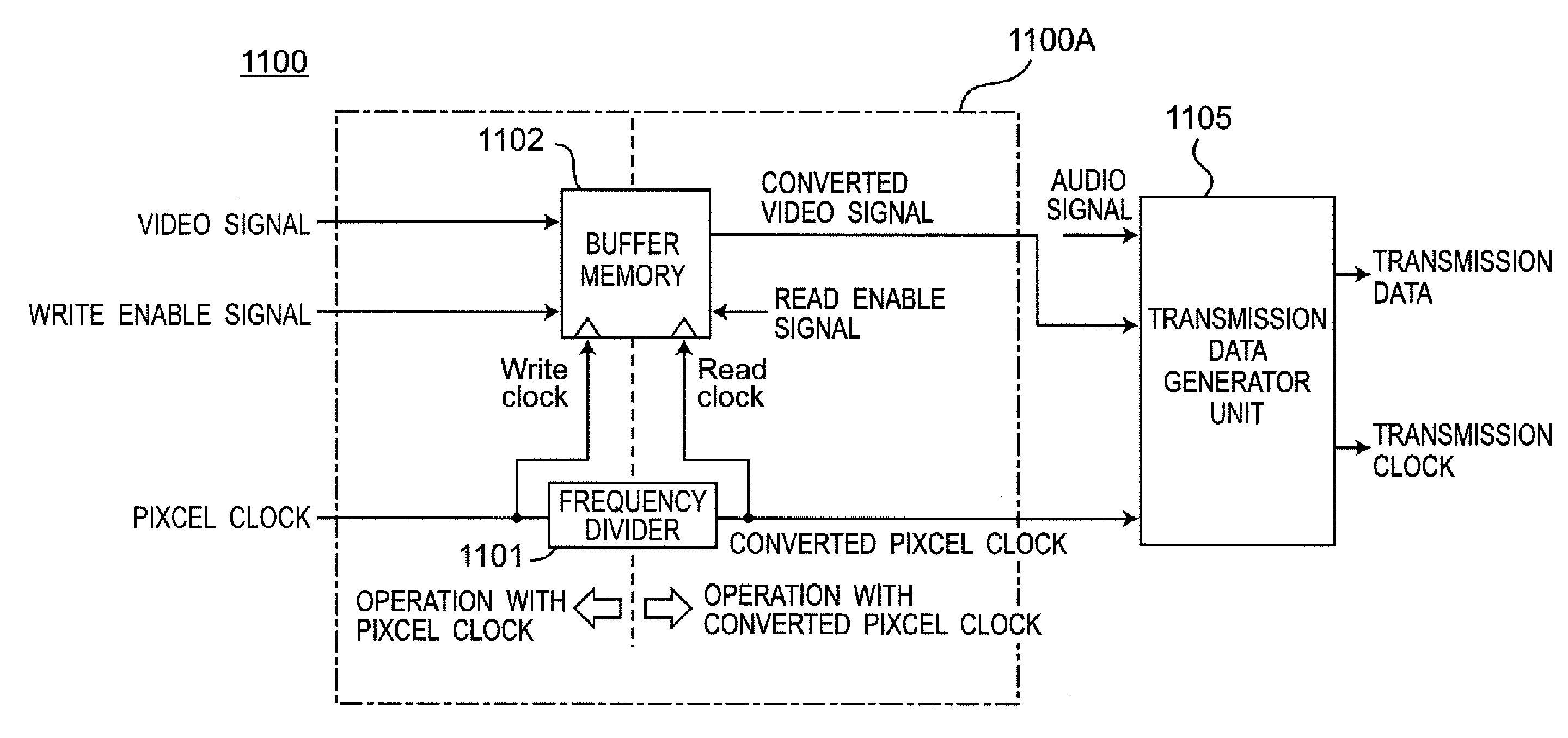
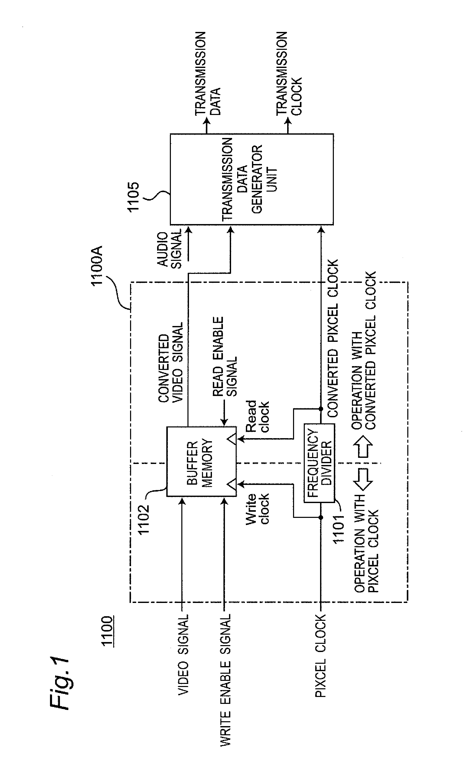
[0037]FIG. 1 is a block diagram showing a configuration of a video signal transmitter apparatus 1100 according to a first embodiment of the present disclosure. Referring to FIG. 1, the video signal transmitter apparatus 1100 is configured to include a video signal transmitter unit 1100A, and a transmission data generator unit 1105, where the video signal transmitter unit 1100A is configured to include a frequency divider 1101, and a buffer memory 1102.

[0038]Referring to FIG. 1, a pixel clock having the same transmission rate as that of the video signal is inputted to the frequency divider 1101, the frequency divider 1101 performs frequency division on the input pixel clock with a predetermined ratio of transmission frequency division which will be described in detail later, and outputs the pixel clock after the frequency division as a converted pixel clock to the buffer memory 1102 and the transmission data generator uni...

second embodiment

3. Second Embodiment

3-1. Video Signal Transmitter Apparatus 1200

[0056]FIG. 4A is a block diagram showing a configuration of a video signal transmitter apparatus 1200 according to a second embodiment of the present disclosure. Referring to FIG. 4A, the video signal transmitter apparatus 1200 is configured to include a video signal transmitter unit 1200A, and a transmission data generator unit 1205. In this case, the video signal transmitter unit 1200A is configured to include a frequency divider 1201, a buffer memory 1202, a memory control signal generator circuit 1203, and a converted horizontal synchronizing signal generator circuit 1204. The frequency divider 1201 and the buffer memory 1202 operate fundamentally in manners similar to those of the frequency divider 1101 and the buffer memory 1102 of the first embodiment, respectively. It is noted that FIG. 4A shows the transmission data generator unit 1205 outputs a transmission clock, however, encoding suitable for clock regenerat...

third embodiment

4. Third Embodiment

4-1. Video Signal Transmitter Apparatus

[0088]FIG. 8 is a table showing a method of setting a ratio of transmission frequency division of each of signal formats for transmission data according to the third embodiment of the present disclosure. The third embodiment will be described to deal with a plurality of signal formats for transmission data having resolutions different from each other by the same video signal transmitter apparatus and the same video signal receiver apparatus. The configuration of the video signal transmitter apparatus according to the present embodiment is the same as that of the second embodiment, and the third embodiment is characterized by a method of setting the number of horizontal pixels of the converted video signal and the ratio of transmission frequency division of the frequency divider 1201. With reference to the example of a table of FIG. 8, the method of setting the number of horizontal pixels and the ratio of transmission frequenc...


PUM


Abstract

In a video signal transmitter apparatus that removes a part of a blanking interval of a video signal, generates a converted video signal, based on the video signal including an active interval including video data and the blanking interval excluding the video data, a frequency divider divides a frequency of a pixel clock in synchronization with the video signal by a ratio of transmission frequency division, generate and output a frequency-divided clock as a converted pixel clock. A controller controls a first storage unit to write the video signal for the active interval of the video signal, and read the video signal for the active interval of the converted video signal and output a read video signal as the converted video signal, and to remove a part of a signal included in a horizontal blanking interval existing periodically every horizontal line for the blanking interval of the video signal.

Description

CROSS-REFERENCE TO RELATED APPLICATIONS[0001]This is a continuation application of International Application No. PCT / JP2013 / 000492, with an international filing date of Jan. 30, 2013, which claims priority of Japanese Patent Application No. JP2012-084788 filed on Apr. 3, 2012, the content of which is incorporated herein by reference.BACKGROUND OF THE INVENTION[0002]1. Field of the Invention[0003]The technical field relates to a video signal transmitter apparatus, a video signal transmitting method, a video signal receiver apparatus, and a video signal receiving method, each using uncompressed transmission system for video signals, such as HDMI (High-Definition Multimedia Interface).[0004]2. Description of the Related Art[0005]Conventionally, as an uncompressed transmission system for a video signal, HDMI has been widely used. The video signal transmitter apparatus of HDMI converts video signals of three channels (RGB signals or a luminance signal and color difference signals) among ...

Claims


Application Information

Patent Timeline
IPC IPC(8): H04N5/38H04N5/44
CPCH04N5/44H04N5/38H04N7/08H04N7/0102H04N21/43635G09G5/005G09G5/006G09G5/18G09G2340/0435G09G2350/00G09G2370/12G09G5/00
Inventor IKUSHIMA, TSUYOSHISHIBATA, OSAMU
Owner PANASONIC INTELLECTUAL PROPERTY MANAGEMENT CO LTD
Why Eureka
Try Eureka