Autostereoscopic 3D image display device for flattening viewing zone and minimizing dynamic crosstalk

Active Publication Date: 2015-01-15
KOREA INST OF SCI & TECH
View PDF7 Cites 26 Cited by
  • Summary
  • Abstract
  • Description
  • Claims
  • Application Information

AI Technical Summary

Benefits of technology

[0022]According to embodiments of the present invention, it is possible to dynamically minimize crosstalk at a viewer's pupil even when the viewer moves in a 3D space including a viewpoint of each 3D pixel line, which is generated by a method of arranging the parallax barrier, t

Problems solved by technology

However, in conventional 3D image display devices using the parallax barrier, the lenticular lens, and the line light source array for forming the viewing zone, brightness of a corresponding viewpoint image varies with movement of eyes even in the same viewing zone, and also crosstalk, which is partial overlap of an image of an adjacent viewpoint, occurs.
Accordingly, it is difficult to implement a natural 3D image when a viewer moves, thereby causing viewer inconvenience.
Further, since the distance between viewpoints is designed to be appropriate for a distance between an average viewer's pupils even when the viewer stops, left and right optimal bright images cannot be viewed

Method used


Image

  • Autostereoscopic 3D image display device for flattening viewing zone and minimizing dynamic crosstalk
  • Autostereoscopic 3D image display device for flattening viewing zone and minimizing dynamic crosstalk
  • Autostereoscopic 3D image display device for flattening viewing zone and minimizing dynamic crosstalk

Examples


Example

MODES OF THE INVENTION

[0048]Hereinafter, preferred embodiments of the present invention will be described in detail with reference to the accompanying drawings. However, the following embodiments are provided for those skilled in the art to fully understand the present invention and thus may be embodied in different forms. Accordingly, the present invention should not be construed as limited to the embodiments set forth herein.

[0049]A shape of a viewpoint generated by an autostereoscopic 3D image display device, an implementation method thereof, and a method of dynamically controlling a 3D image with movement of a viewer will be described below with reference to FIGS. 2 to 13.

[0050]The present embodiment describes a method of dynamically providing a 3D image only when a viewer does not significantly leave the designed optimal viewing distance. An image control method when the viewer significantly leaves the optimal viewing position will be described below in another embodiment.
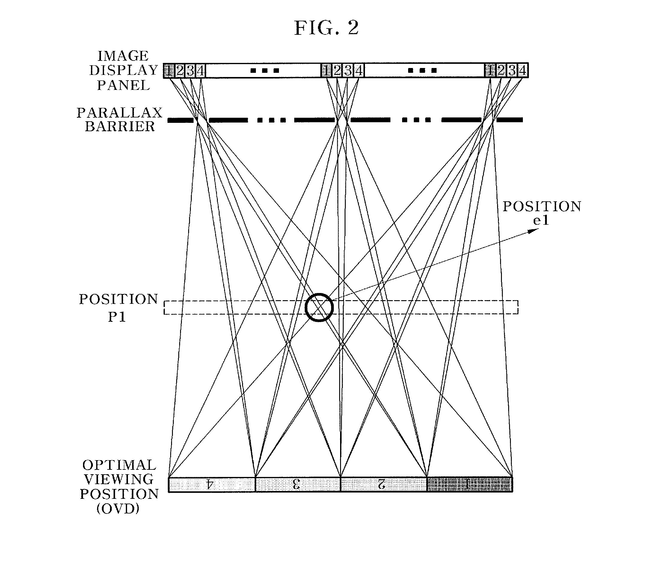
[0051...


PUM


Abstract

The present invention relates to a 3D image display device and includes an image display panel for displaying a 3D image, a control unit for controlling a viewpoint image, and a viewer position tracking system for determining the position of a viewer's pupil and transmitting positional information to the control unit, wherein the image display panel provides multiple viewpoints such as four or more viewpoints, and the intersection of the viewing zone for any one of the multiple viewpoints with the field of view of an adjacent viewpoint is at least 85% of the maximum brightness of one viewpoint.

Description

TECHNICAL FIELD[0001]The present invention relates to an autostereoscopic three-dimensional (3D) image display device, and more particularly, to a 3D image display device that can dynamically minimize crosstalk at a viewer's pupils and minimize change in brightness of a 3D image even when the viewer is moving, by flattening a viewing zone brightness distribution of a viewpoint image generated by arranging a parallax barrier, which is an optical plate for forming a viewing zone, a lenticular lens, or a line light source, overlapping a flattened viewing zone of an adjacent viewpoint, tracking a viewer's position in real time, providing viewpoint images at viewpoints of the viewer's pupils, and removing an adjacent viewpoint image.BACKGROUND ART[0002]Autostereoscopic 3D image display devices are classified into a type using an optical plate, such as a lenticular lens or parallax barrier, and a type using a line light source array for forming a viewing zone. However, in conventional 3D ...

Claims


Application Information

Patent Timeline
IPC IPC(8): H04N13/04G02B30/25G02B30/32
CPCH04N13/0468H04N13/0402G02B27/0093H04N13/31H04N13/351G02B30/32G02B30/25H04N13/302H04N13/366G02B30/27
Inventor KIM, SUNG KYUYOON, KI HYUK
Owner KOREA INST OF SCI & TECH
Why Eureka
Try Eureka