
Device and method for acoustic communication and/or perception in a motor vehicle
a technology for acoustic communication and motor vehicles, applied in electrical transducers, substation equipment, gain control, etc., can solve problems such as increasing quality and compromising installation location and emission characteristics
- Summary
- Abstract
- Description
- Claims
- Application Information
AI Technical Summary
Benefits of technology
Problems solved by technology
Method used
Image

Examples
Embodiment Construction
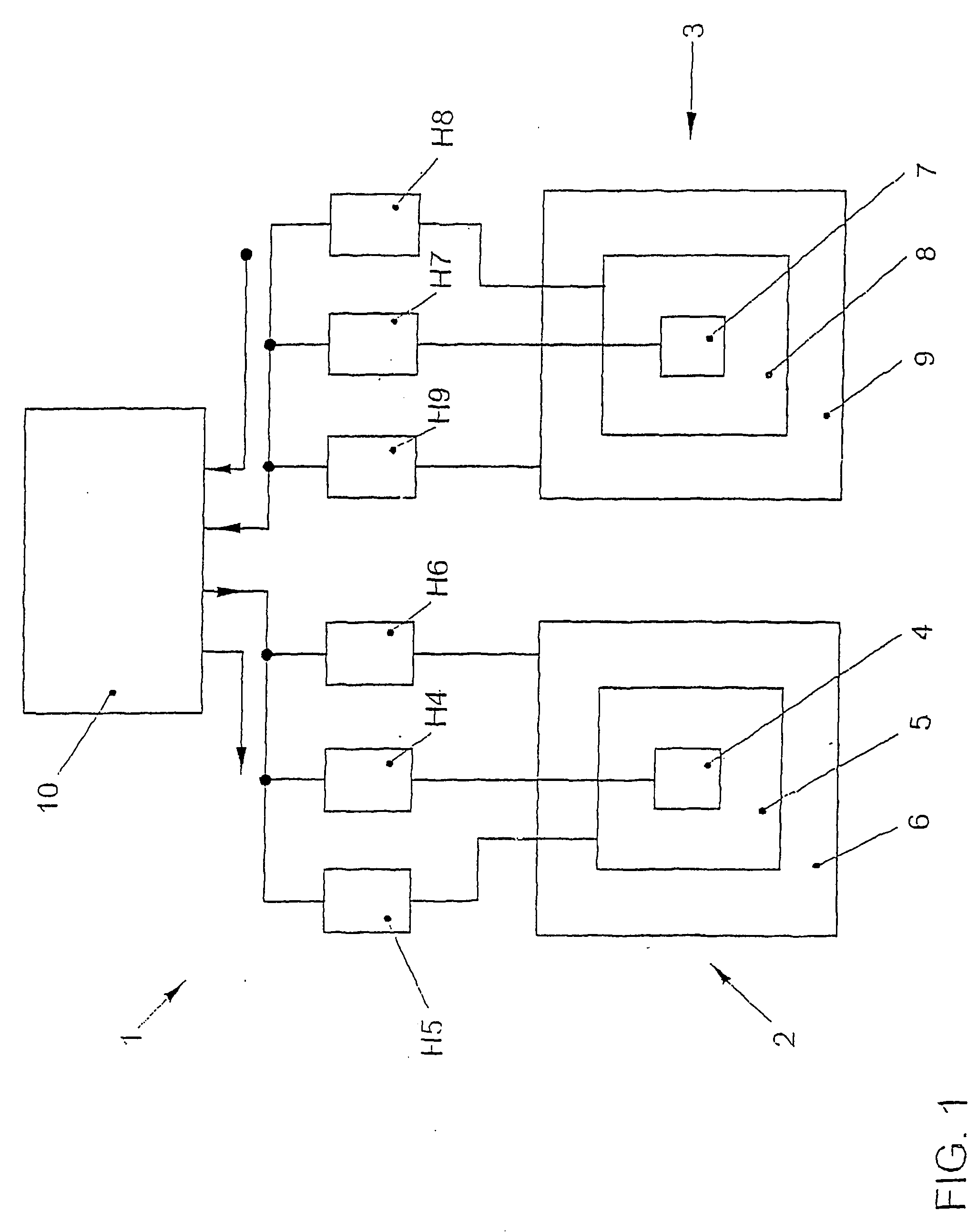
[0034]Device 1 includes a directional loudspeaker 2 and a directional microphone 3. Directional loudspeaker 2 is made up of three electrostatic planar loudspeakers 4-6. Directional microphone 3 is made up of three electrostatic planar microphones 7-9. One complex transmission function H4(f)-H6(f) is assigned to each of the planar loudspeakers 4-6. Correspondingly, one complex receiving function H7(f)-H9(f) is assigned to each of the planar microphones 6-8. The three respective planar loudspeakers 4-6 and planar microphones 7-9 are concentrically arranged with respect to one another. Device 1 furthermore includes an audio processor 10. Beam forming may be achieved via complex transmission functions H4(f)-H6(f) such that minor lobes of directional loudspeaker 2 are minimized. The same applies to receiving functions H7(f)-H9(f) of directional microphone 3. These are selected such that a very narrow major lobe results for the emission and receiving characteristics with respect to the as...
PUM
 Abstract
Description
Claims
Application Information