Display device and television receiver
- Summary
- Abstract
- Description
- Claims
- Application Information
AI Technical Summary
Benefits of technology
Problems solved by technology
Method used
Image

Examples
embodiment 1
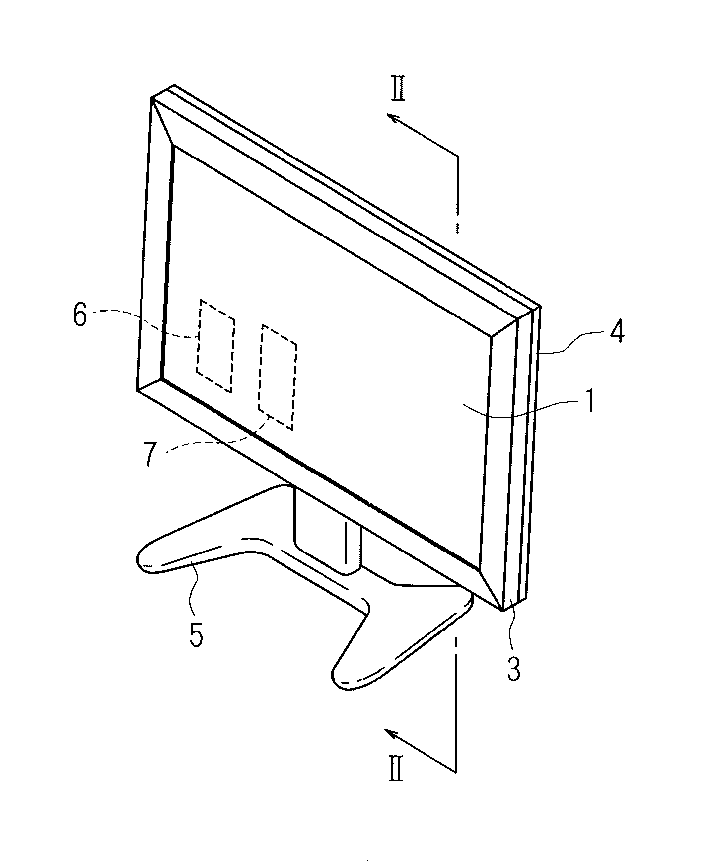
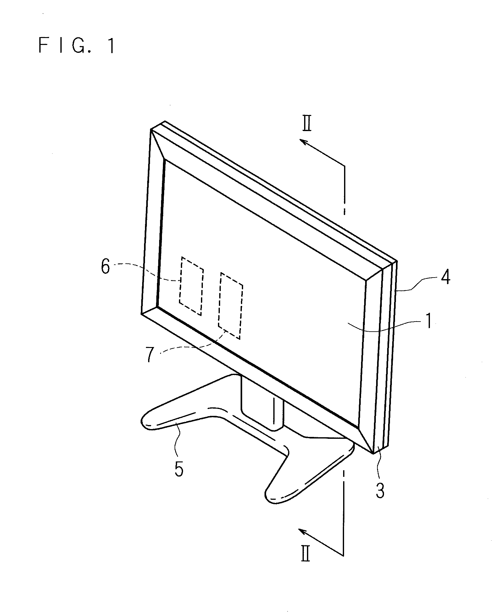
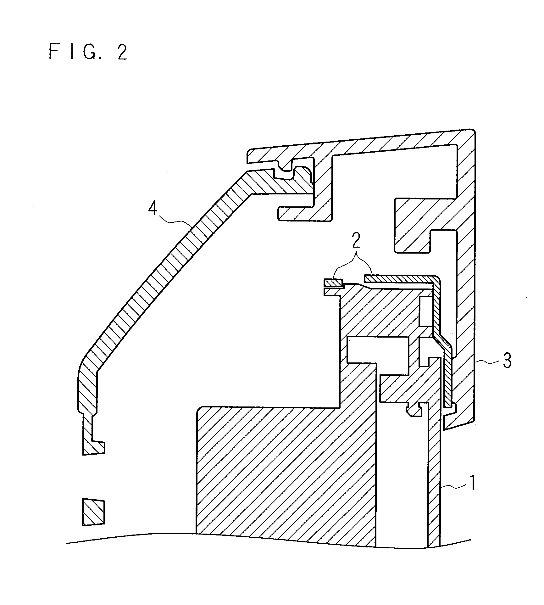
[0038]FIG. 1 is an appearance perspective view illustrating a configuration example of a television receiver according to Embodiment 1. FIG. 2 is simplified cross sectional view illustrating a cross section taken from II-II in FIG. 1, in which a main part is enlarged. In FIG. 2, the illustration is simplified as its object is to show the positional relation of main parts. The television receiver comprises a display panel unit 1, a bezel 2, a front cabinet 3, a rear cabinet 4, a stand 5, a tuner part 6 (receiving part), and a signal processing part 7.
[0039]The display panel unit 1 is configured to comprise a rectangular plate-shaped liquid crystal panel, control a voltage applied to the liquid crystal for adjusting a light transmittance, and display an image on the front of the display panel unit 1.
[0040]The bezel 2 has a rectangular frame-like shape and is positioned so as to cover a circumferential part of the display panel unit 1. The bezel 2 supports an upper side, a lower side a...
embodiment 2
[0060]FIG. 7A and FIG. 7B are perspective views illustrating an example of shapes of end parts of frame members 34, 35 constituting a front cabinet 3 according to Embodiment 2. FIG. 7A illustrates the end part viewed from the inside of a television receiver. FIG. 7B illustrates the end part viewed from the outside of the television receiver.
[0061]As illustrated in FIGS. 7A and 7B, the frame member 34 comprises a recessed part 34a and projected parts 34b, 34c. As illustrated in FIG. 7A, the frame member 35 comprises a projected part 35a and recessed parts 35b, 35c.
[0062]The frame member 34 is, for example, a rod-shaped member which is formed by extrusion processing of aluminum and has an L-shaped cross section. At the end part of the frame member 34, a plate-like part 34d having a wider width is diagonally cut by about a half of the thickness of the plate-like part 34d at a predetermined angle (approximately 45 degrees). The remaining thickened part forms the projected parts 34b, 34...
embodiment 3
[0069]FIG. 8A and FIG. 8B are perspective views illustrating an example of shapes of end parts of frame members constituting a front cabinet 3 according to Embodiment 3. FIG. 8A illustrates the end parts viewed from the inside of a television receiver. FIG. 8B illustrates the end parts viewed from the outside of the television receiver.
[0070]As illustrated in FIGS. 8A, 8B, a frame member 36 comprises a recessed part 36a, projected parts 36b and 36c. As illustrated in FIG. 8A, a frame member 37 comprises a projected part 37a, recessed parts 37b and 37c.
[0071]The frame members 36, 37 in the present embodiment and the above-mentioned frame members 34, 35 are different in the shapes of projected parts and recessed parts and are similar in the other parts. Accordingly, the different points are mainly described.
[0072]The recessed part 36a of the frame member 36 and the projected part 37a of the frame member 37 are each formed into a substantially parallelogrammic shape. The projected par...
PUM
 Abstract
Description
Claims
Application Information