Dissipative Soliton Mode Fiber Based Optical Parametric Oscillator

Active Publication Date: 2015-01-15
CANON KK +1
View PDF8 Cites 16 Cited by
  • Summary
  • Abstract
  • Description
  • Claims
  • Application Information

AI Technical Summary

Benefits of technology

[0021]In an alternative embodiment the signal pulse is a soliton and pulse brea

Problems solved by technology

However, the output pulse energy and peak power of past FOPO have been quite modest.
This implementation avoided the adverse influence of nonlinear e

Method used


Image

  • Dissipative Soliton Mode Fiber Based Optical Parametric Oscillator
  • Dissipative Soliton Mode Fiber Based Optical Parametric Oscillator
  • Dissipative Soliton Mode Fiber Based Optical Parametric Oscillator

Examples


Example

First Exemplary Embodiment

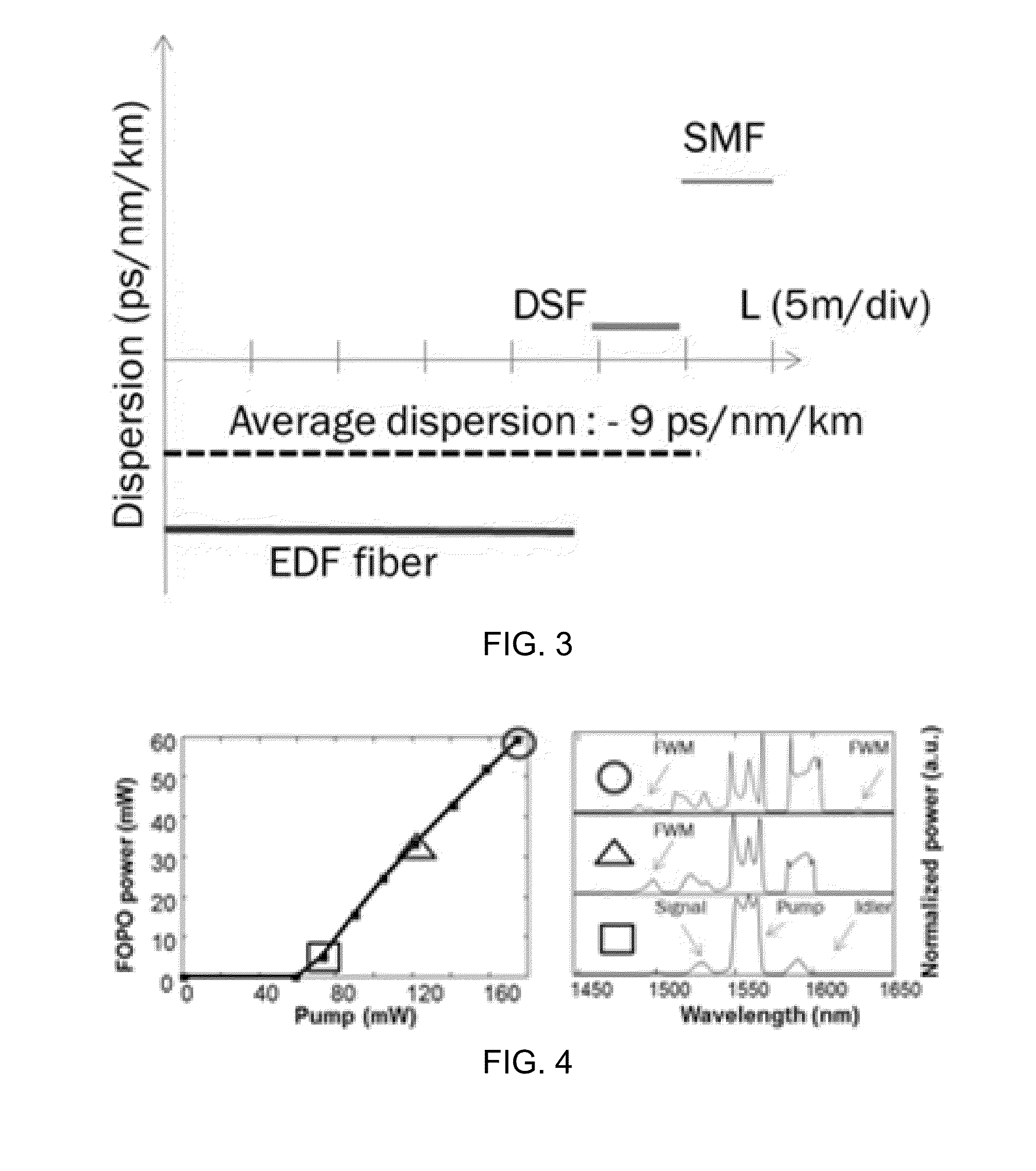
[0044]A first exemplary embodiment is a synchronously pumped fiber optical parametric oscillator (FOPO) operating in the normal dispersion regime. The FOPO generates chirped pulses at the output allowing significant pulse energy scaling potential without pulse-breaking. The average output power of the FOPO at 1600 nm was ˜60 mW; corresponding to 1.45 nJ pulse energy and ˜55% slope power conversion efficiency. The output pulses directly from the FOPO were highly chirped (˜3 ps duration) and could be compressed outside of the cavity to 180 fs by using a standard optical fiber compressor having anomalous dispersion.

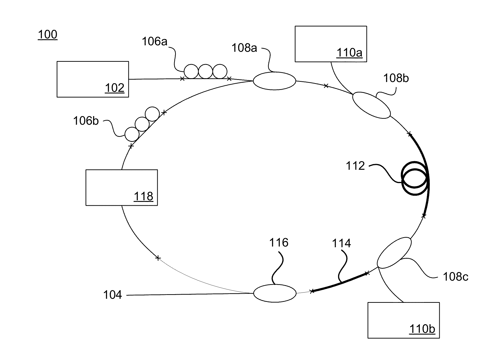
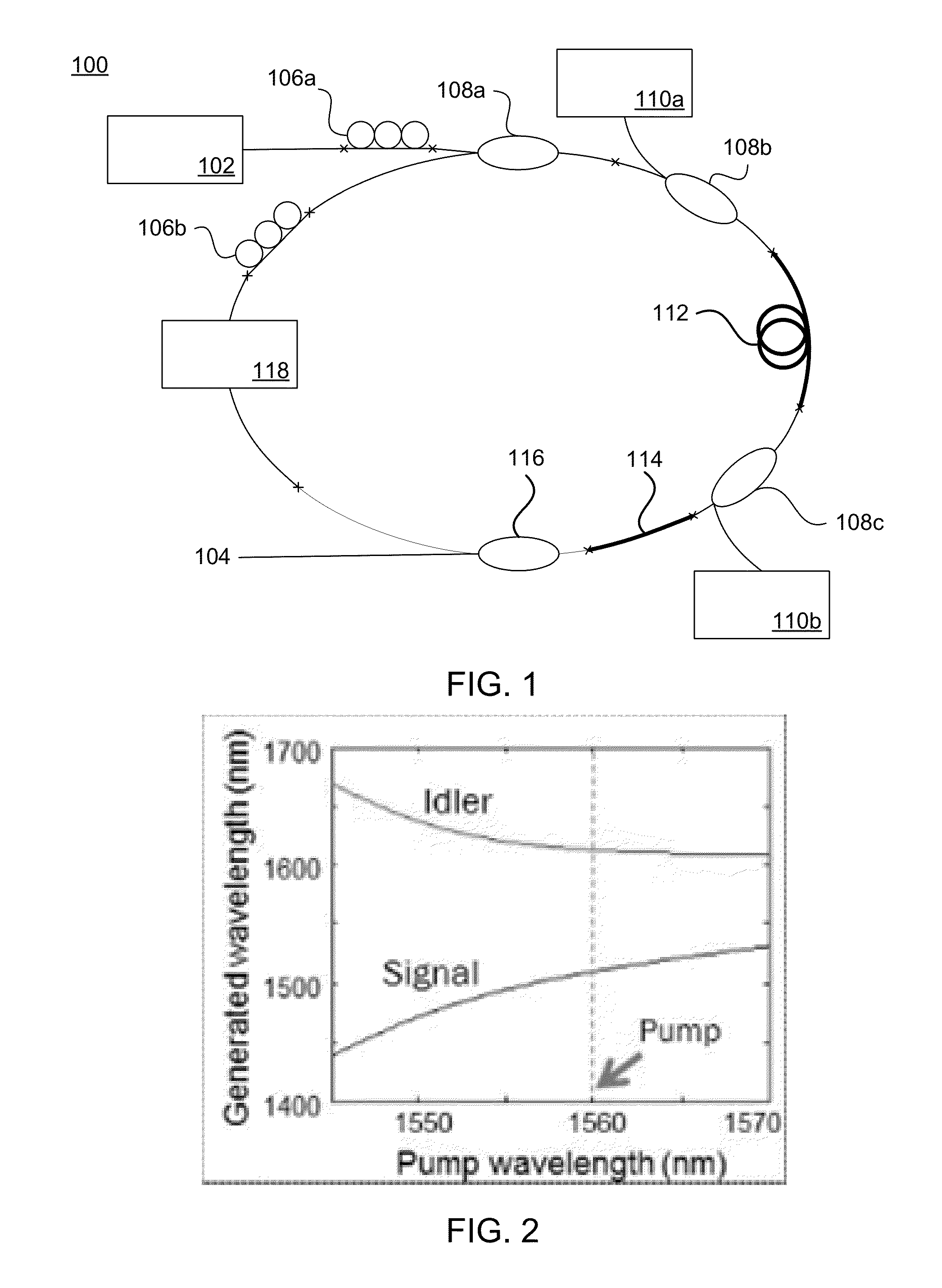
[0045]A first exemplary embodiment 100 is a synchronously pumped FOPO operating in the normal dispersion regime and is pumped by a pump source (seed laser, pump laser) 102 which may be a compact Er-doped femtosecond fiber laser as illustrated in FIG. 1. The FOPO generated chirped pulses at an output 104 allowing significant pulse energy scaling pote...

Example

Second Exemplary Embodiment

[0060]A second exemplary embodiment 700 is described with reference to FIG. 7. Configurations common to those of the first exemplary embodiment 100 will be denoted by the same reference numerals as those of the first exemplary embodiment and the description thereof will be omitted.

[0061]The second exemplary embodiment 700 is identical the first exemplary embodiment 100 except that it does not include the EDFA. The second exemplary embodiment 700 further includes single mode fiber 720.

Numerical Simulation of First Exemplary Embodiment

[0062]A numerical simulation using realistic experimental parameters can be used to simulate the formation as well as the evolution of the idler pulses around the FOPO cavity. A model maybe built based on the nonlinear Schrodinger equation. A fourth order Runge-Kutta in the interaction picture (RK4-IP) method may be used to solve the equation numerically. The pump pulses were assumed to have a Gaussian shape. The resonating idl...

Example

[0108]A third exemplary embodiment is a specific example of the second embodiment 700 described above. In which the zero-dispersion wavelength is 1050 nm, a 3rd order dispersions of the HNLF 114 for parametric gain is 6.71776E-41 s3 / m, and 4th order dispersion of HNLF 114 for parametric gain is −9.83483E-56 s4 / m. For the pump pulse produced by the pump laser 102, the output wavelength is 1040 nm, the average power is 4 W, the repetition rate is 15 MHz, the temporal pulse width is 10 ps, and the spectral width is 0.11 nm.

[0109]FIGS. 9A-B show the simulated results of the evolution of the gain spectrum width depending on the HNLF 114 length LHNLF as the wavelength of pump pulse is changed from 1040 nm to 1060 nm. As illustrated in FIG. 9A when the center wavelength of pump pulse is 1040 nm and LHNLF is 0.01 m the signal gain spectrum is 763 nm to 804 nm. As illustrated in FIG. 9B when the center wavelength of pump pulse is 1040 nm and LHNLF is 0.01 m the idler gain spectrum is 1469 nm...


PUM


Abstract

A fiber optic parametric amplifier that includes a resonating cavity. The resonating cavity includes linear fiber optic gain medium, with negative chromatic dispersion; and a nonlinear fiber optic gain medium with positive chromatic dispersion.

Description

CROSS REFERENCE TO RELATED APPLICATION[0001]This application claims the benefit of U.S. Provisional Application No. 61 / 845,767, filed Jul. 12, 2013 and U.S. Provisional Application No. 61 / 953,434, filed Mar. 14, 2014. U.S. Provisional Application Nos. 61 / 845,767 and 61 / 953,434 are herein incorporated by reference in their entirety.BACKGROUND[0002]1. Field of Art[0003]This disclosure generally relates to fiber based optical parametric oscillators.[0004]2. Description of the Related Art[0005]Light sources based on optical parametric interaction are interesting since they provide access to laser wavelengths that existing gain materials based on electronic transitions cannot provide. An optical parametric oscillator (OPO) can be realized by exploiting the x(2) nonlinear optical response in a wide range of crystals or the x(3) nonlinear response in optical fibers.[0006]Optical fiber based OPO (FOPO) are particularly attractive owning to their potential in achieving low cost, alignment-fr...

Claims


Application Information

Patent Timeline
IPC IPC(8): G02F1/39
CPCG02F1/395G02F2001/392G02F2201/02G02F2203/15G02F1/3542G02F1/392H01S3/0092
Inventor KIEU, KHANHNGUYEN, THANH NAMPEYGHAMBARIAN, NASSEROTA, TAKEFUMI
Owner CANON KK
Why Eureka
Try Eureka