
Multi-input and multi-output communication method in large-scale antenna system

Active Publication Date: 2015-01-15
ELECTRONICS & TELECOMM RES INST
View PDF3 Cites 147 Cited by
  • Summary
  • Abstract
  • Description
  • Claims
  • Application Information

AI Technical Summary

Benefits of technology

The present invention relates to a multi-input multi-output (MIMO) transmission and reception method that allows for independent scheduling of user equipment (UE) groups with virtual sectors. This reduces system complexity for performing multi-user MIMO. The method also introduces group-specific reference signals (GRSs) which facilitate the effective performance of MU-MIMO. Furthermore, the method allows for the use of an adaptive codebook for the UE, ensuring better performance than a fixed codebook, such as LTE. Additionally, the method reduces the load of resource allocation and feedback from the UE due to GRSs and the adaptive codebook.

Problems solved by technology

Existing large-scale antenna systems have been limited to a time-division duplex (TDD) scheme.
This is because a frequency-division duplex (FDD) scheme has a problem that a large-scale antenna transmitter requires as many reference signals (RSs) and radio resources for CSI feedback as substantially impossible to obtain CSI.
In addition, since the number of users that can be simultaneously accommodated by a large-scale transmitting antenna remarkably increases, there occurs a practical problem in that the complexity of scheduling and precoding calculation becomes very higher than that of an existing system.

Method used


Image

  • Multi-input and multi-output communication method in large-scale antenna system
  • Multi-input and multi-output communication method in large-scale antenna system
  • Multi-input and multi-output communication method in large-scale antenna system

Examples


Embodiment Construction

[0039]While the present invention can be modified in various ways and take on various alternative forms, specific embodiments thereof are shown in the drawings and described in detail below as examples.

[0040]However, there is no intent to limit the present invention to the particular forms disclosed. On the contrary, the present invention is to cover all modifications, equivalents, and alternatives falling within the spirit and scope of the appended claims.

[0041]The terminology used herein to describe embodiments of the invention is not intended to limit the scope of the invention. Singular forms include plural forms unless the context clearly indicates otherwise. It will be further understood that the term “comprises,”“comprising,”“includes,” or “including,” when used herein, specifies the presence of stated features, integers, steps, operations, elements, components, or groups thereof, but do not preclude the presence or addition of one or more other features, integers, steps, ope...


PUM


Abstract

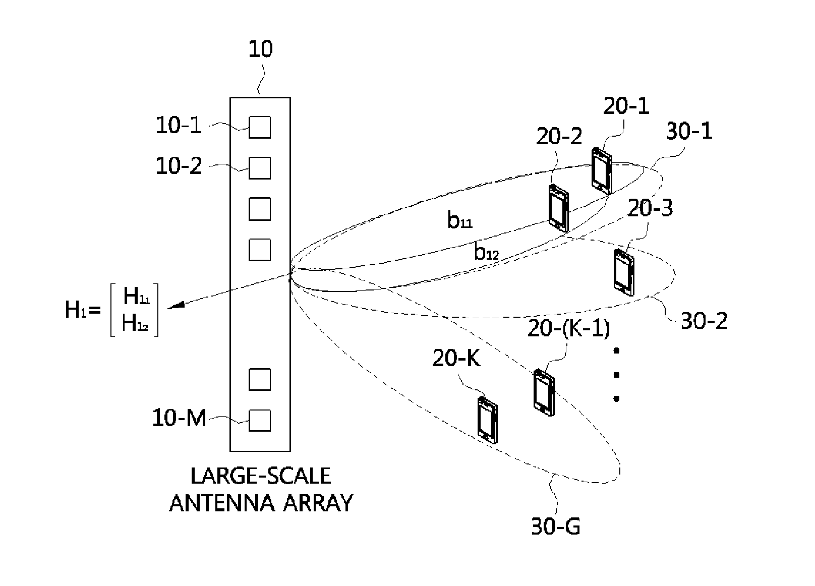
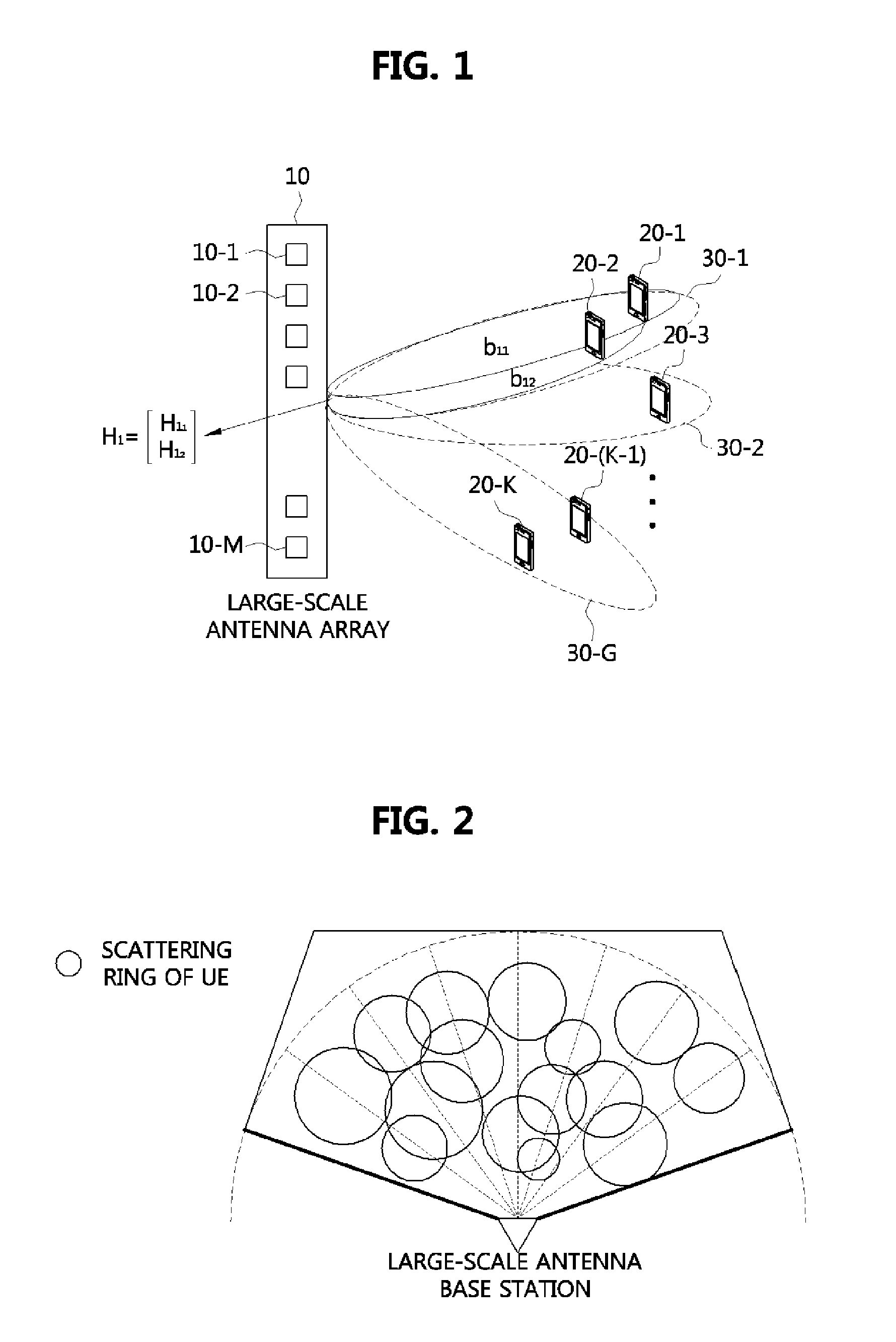
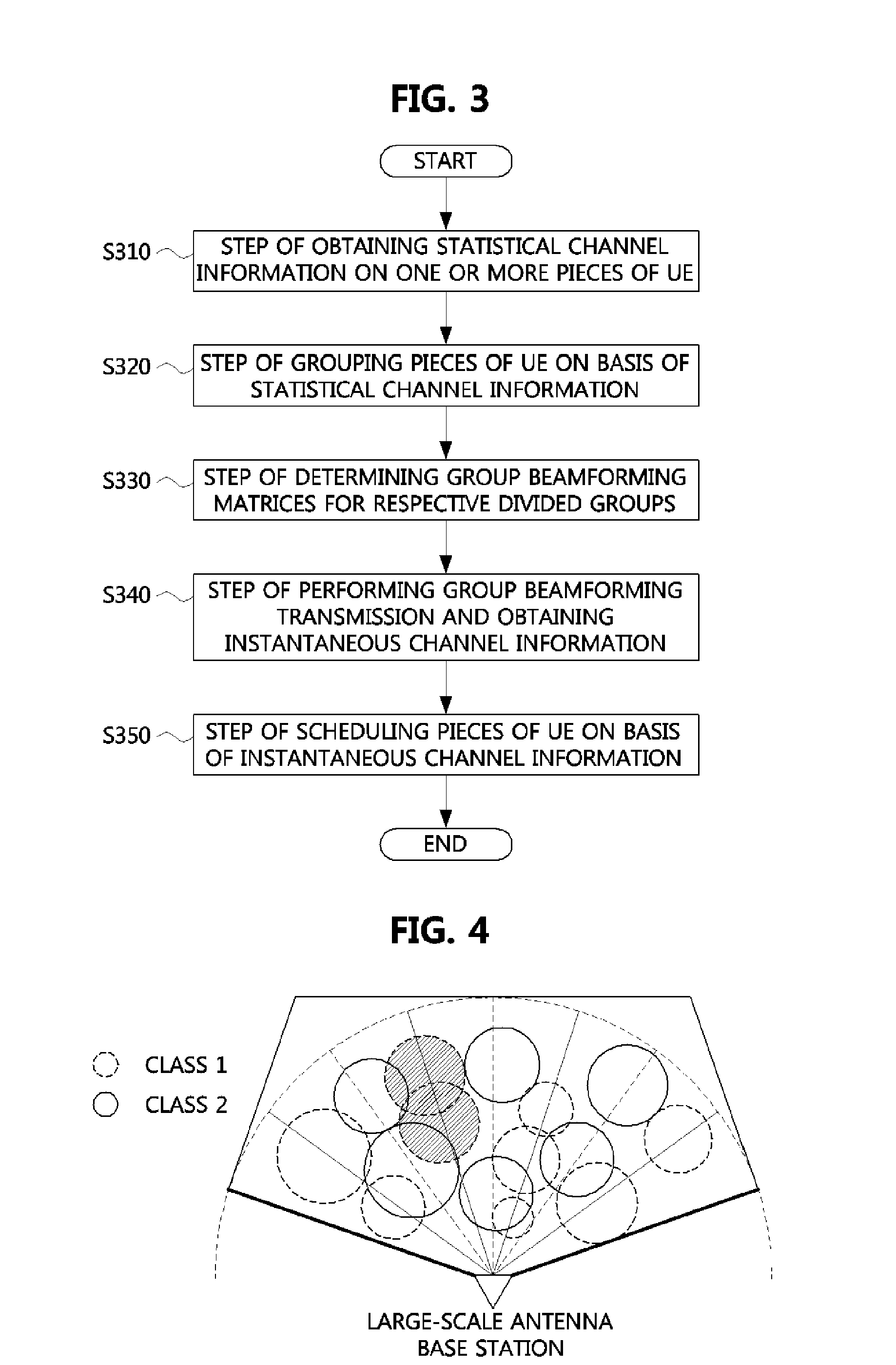
The present invention relates to a multi-input and multi-output communication method in a large-scale antenna system. An MIMO transmission method according to the present invention includes: obtaining statistical channel information on at least one terminal, dividing terminals into a plurality of classes and a plurality of groups based on the statistical channel information, wherein the groups depend on the classes; determining a group beam-forming matrix for each of the divided groups; performing a group beamforming transmission by group based on the group beam-forming matrix to obtain instantaneous channel information; and scheduling terminals based on the instantaneous channel information. Thus, it is possible to decrease the complexity in a scheduling and precoding calculation without an increase in the amount of wireless resources that are required for providing feedback for a reference signal and channel status information.

Description

TECHNICAL FIELD[0001]The present invention relates to a multi-input multi-output (MIMO) communication method in a large-scale antenna system, and more particularly, to an MIMO communication method that maximizes up-downlink frequency efficiency in a correlated large-scale MIMO channel environment while requiring feedback of a small amount of channel state information (CSI).BACKGROUND ART[0002]Due to a drastic increase in data traffic, a Beyond-Fourth-Generation (B4G) mobile communication system requires 10 times an increase in frequency efficiency or more compared to a 4G system such as Third Generation Partnership Project (3GPP) Long Term Evolution (LTE). As physical layer techniques necessary to increase frequency efficiency 10 times or more as stated above, network MIMO, interference alignment, relay network, heterogeneous network, a large-scale MIMO technique, etc. are currently being mentioned.[0003]The present invention relates to a massive MIMO (or large-scale antenna) system...

Claims


Application Information

Patent Timeline
IPC IPC(8): H04B7/04H04B7/06H04W72/12
CPCH04B7/0617H04B7/0482H04W72/1226H04B7/0452H04B7/0456H04B7/0619H04B7/0634H04B7/0639H04W72/54H04B7/0469H04B7/0478H04B7/0479H04B7/0421H04B7/043H04B7/0626H04L1/0026H04L25/0224H04W72/121H04B7/0413H04B15/00H04L5/0048
Inventor NAM, JUN YOUNGAHN, JAE YOUNG
Owner ELECTRONICS & TELECOMM RES INST
Learn More