Wiper for vehicle

a technology for wipers and vehicles, applied in the field of vehicle wipers, can solve the problems of difficult opening of the attachment-separation port of the shaft support recess, and the difficulty of reducing the size of the wiper blade in the heightwise direction, so as to reduce the size and limit the opening of the attachment-separation por

Active Publication Date: 2015-01-22
DENSO CORP
View PDF4 Cites 4 Cited by
  • Summary
  • Abstract
  • Description
  • Claims
  • Application Information

AI Technical Summary

Benefits of technology

[0005]In the vehicle wiper described in patent document 2, to reduce the size of wiper blade in the heightwise direction (direction perpendicular to the wiping surface), the portion coupling the wiper arm and the wiper blade may be reduced in height without changing the diameters of the support shaft and the coupling hole. This would reduce the thickness around the coupling hole at the distal end of the wiper arm. Thus, if the wiper arm were to be formed, in particular, from resin or the like, deformation may result in a tendency of easy opening of the attachment-separation port in the coupling hole, which is used for attachment and separation of the support shaft. The support shaft may thus fall out of the attachment-separation port of the coupling hole even if the wiper blade is located at the normal usage position. Hence, in the coupling structure of the support shaft described in patent document 2, it was difficult to reduce the size of the wiper blade in the heightwise direction.
[0006]Accordingly, it is an object of the present invention to provide a vehicle wiper capable of limiting opening of the attachment-separation port of the coupling hole while reducing the size in the heightwise direction.

Problems solved by technology

Thus, if the wiper arm were to be formed, in particular, from resin or the like, deformation may result in a tendency of easy opening of the attachment-separation port in the coupling hole, which is used for attachment and separation of the support shaft.
Hence, in the coupling structure of the support shaft described in patent document 2, it was difficult to reduce the size of the wiper blade in the heightwise direction.
Thus, even if the coupling portion of the wiper arm and the wiper blade is reduced in size in the heightwise direction (direction perpendicular to the wiping surface), the attachment-separation port of the shaft support recess does not easily open.

Method used


Image

  • Wiper for vehicle
  • Wiper for vehicle
  • Wiper for vehicle

Examples


Embodiment Construction

[0030]One embodiment of a vehicle wiper will now be described.

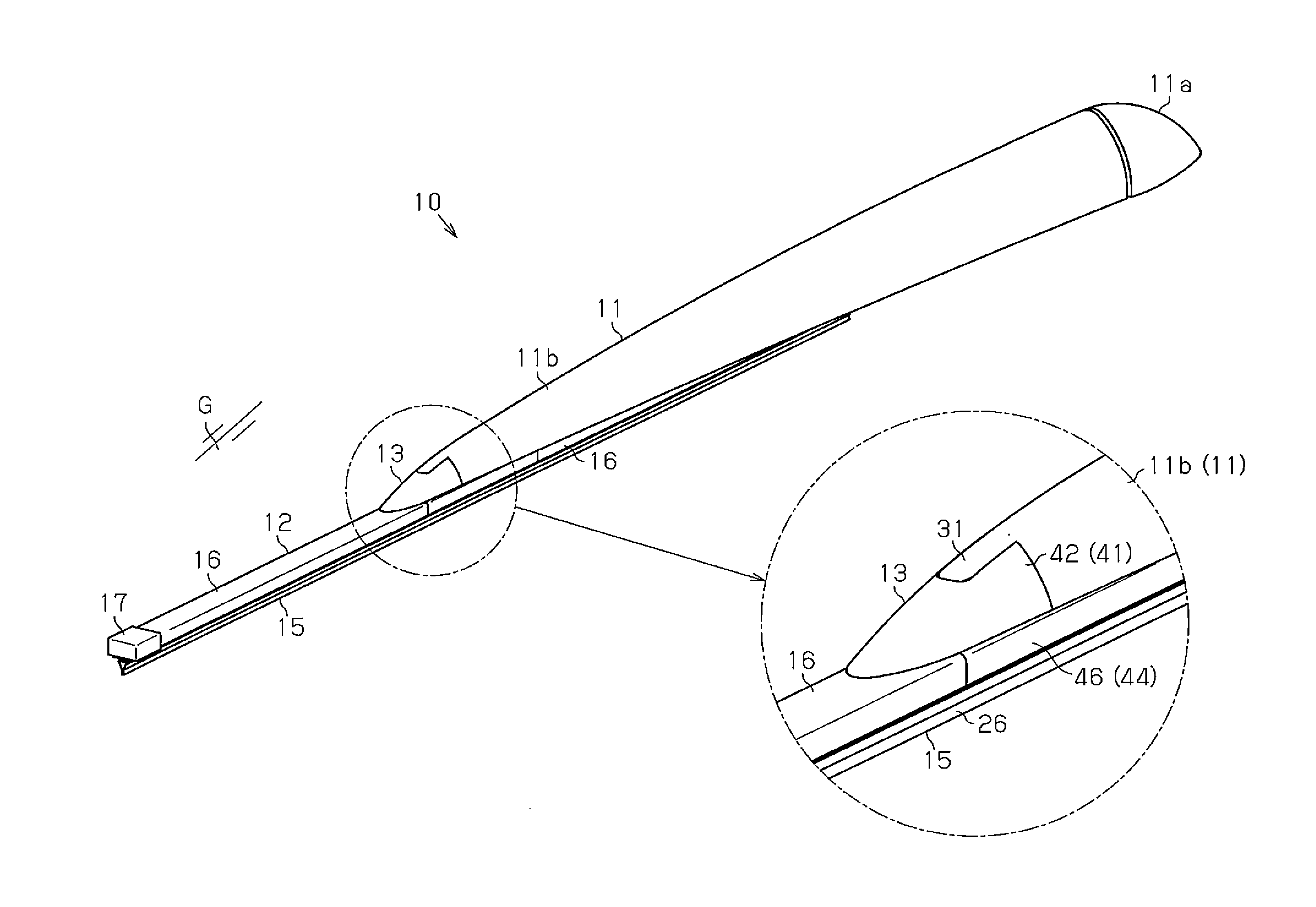
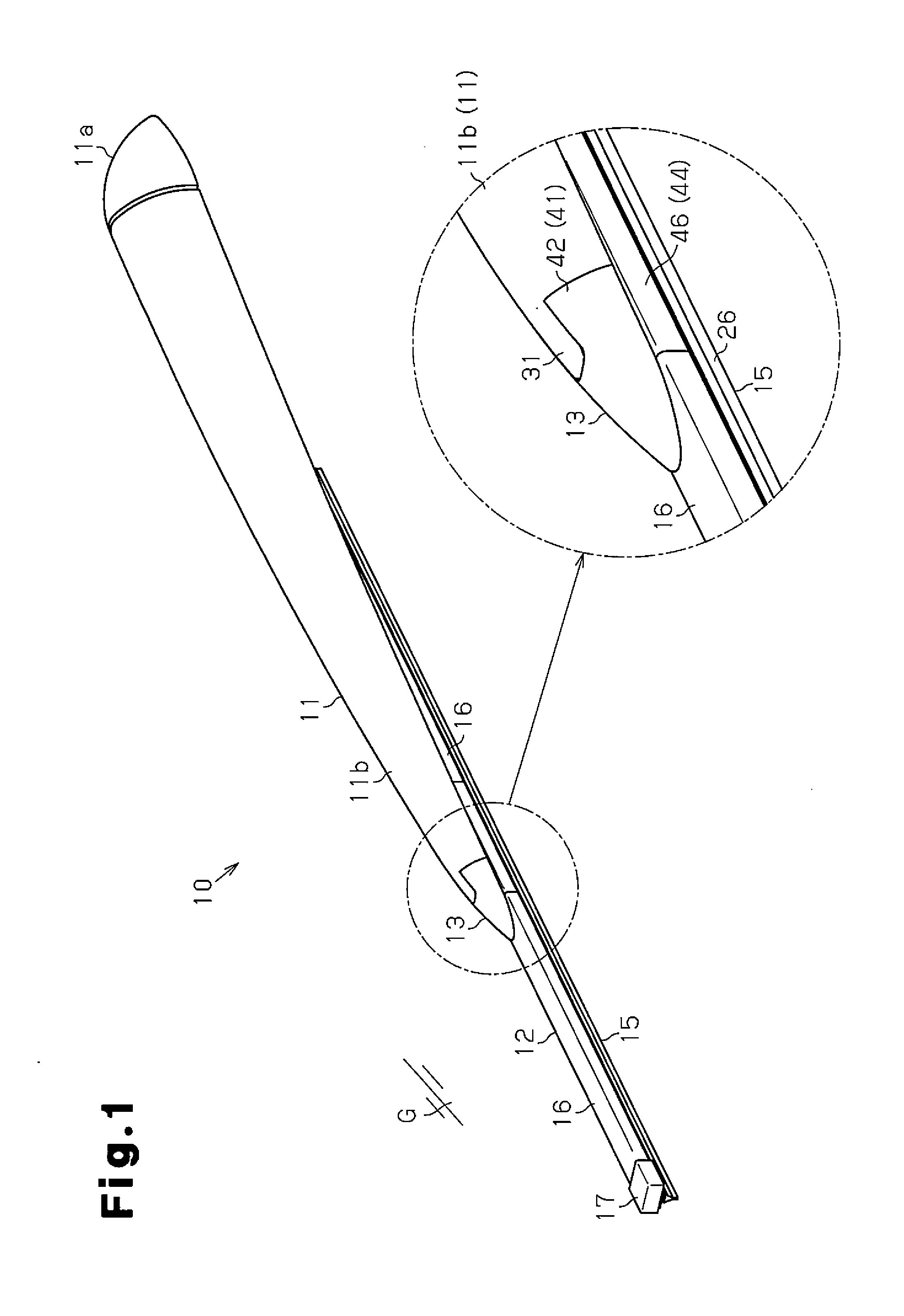
[0031]As shown in FIG. 1, a vehicle wiper 10 according to the present embodiment wipes raindrops or the like from the surface (wiping surface G) of a rear window of a vehicle. The vehicle wiper 10 includes a wiper arm 11, which is formed from resin, and a wiper blade 12, which is pivotally coupled to the distal end of the wiper arm 11 and arranged in contact with the wiping surface G.

[0032]The wiper arm 11 includes a basal end coupled to an arm head 11a, which is fixed to a pivot shaft (not shown). A wiper motor (not shown) drives and pivots the pivot shaft to swing back and forth the wiper arm 11 and the wiper blade 12. The swinging wiper blade 12 wipes the wiping surface G. A spring (not shown), which generates a pushing force pushing the wiper blade 12 against the wiping surface G, is attached to the wiper arm 11.

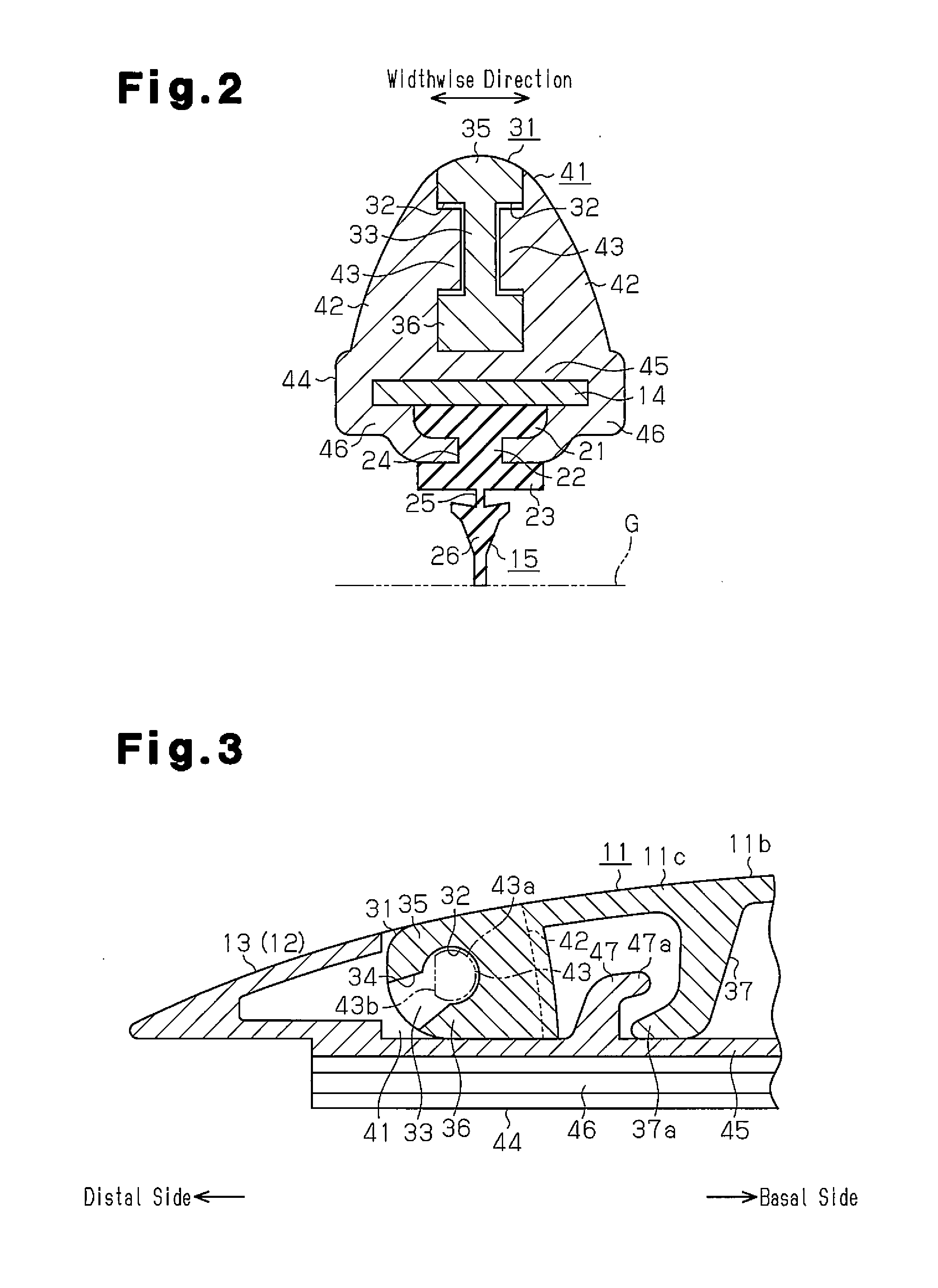
[0033]The wiper blade 12 includes a resin holder member 13, which is coupled to the wiper arm 11, a backing...


PUM


Abstract

A wiper for a vehicle is provided with: an arm-side connection section; a blade-side connection section; support shafts which protrude from side walls of the blade-side connection section; and shaft support recesses which are provided in the arm-side connection section. When a wiper blade is located in a mounting-dismounting enabled region, the mounting-dismounting openings and the small-diameter sections of the support shafts match with each other, and the support shafts and the shaft support recesses can be mounted to and dismounted from each other. When the wiper blade is located in a mounting-dismounting disabled region, the mounting-dismounting openings and the small-diameter sections do not match with each other, and the support shafts and the shaft support recesses cannot be mounted to and dismounted from each other. A shape retaining section is located between the pair of the shaft support recesses.

Description

RELATED APPLICATIONS[0001]The present application is a National Phase entry of PCT Application No. PCT / JP2013 / 078693, filed Oct. 23, 2013, which application claims priority to Japanese Application No. 2012-234900, filed Oct. 24, 2012, both of said applications being hereby incorporated by reference in their entirety.FIELD OF THE INVENTION[0002]The present invention relates to a vehicle wiper that wipes a windshield and a rear window of a vehicle.BACKGROUND OF THE INVENTION[0003]In a conventional vehicle wiper, a wiper blade is pivotally coupled to a distal end of a wiper arm so that the wiper blade can follow along a curved wiping surface. For example, in the vehicle wiper of patent document 1, a coupling hole, which extends through the distal end of the wiper arm, is pivotally coupled, through elastic engagement, to a support shaft formed on the wiper blade. In such a structure, the elastic engagement, which couples between the support shaft and the coupling hole facilitates the at...

Claims


Application Information

Patent Timeline
Patent Type & Authority Applications(United States)
IPC IPC(8): B60S1/38
CPCB60S1/3867B60S1/3856B60S1/3863B60S1/3881B60S2001/409B60S1/4064
Inventor UCHIYAMA, KEITAHIRATA, KEI
Owner DENSO CORP
Why Eureka
Try Eureka