Electronic device with environmental monitoring

a technology of environmental monitoring and electronic devices, applied in coupling device connections, optical radiation measurement, instruments, etc., can solve the problems of affecting the measurement effect, unable to enhance computing capabilities, and unable to connect to network subsystems, so as to facilitate the measurement

Inactive Publication Date: 2015-01-22
LEEO
View PDF16 Cites 41 Cited by
  • Summary
  • Abstract
  • Description
  • Claims
  • Application Information

AI Technical Summary

Benefits of technology

[0011]The described embodiments relate to an environmental monitoring device that includes a housing having walls that define a cavity within the housing, and flow vents in at least one of the walls that, during operation of the environmental monitoring device, direct a fluid flow into and out of the cavity. Moreover, the environmental monitoring device includes a sensor mechanism, within the cavity, that provides sensor data based on measurements of an environmental condition in an external environment that includes the environmental monitoring device. Furthermore, the environmental monitoring device includes a processor, within the cavity, that processes the sensor data. The fluid flow is associated with operation of the processor, and the processor is positioned relative to the sensor mechanism so that the fluid flow is directed over the sensor mechanism to facilitate the measurements.

Problems solved by technology

However, the overwhelming majority of the existing background electronic devices in people's homes, offices and vehicles have neither enhanced computing capabilities (such as processor that can execute a wide variety of applications) nor networking subsystems.
These barriers to entry and change are obstacles to widely implementing the Internet of things.
As a consequence, it may also be difficult to extend the advantages of connectivity and enhanced computing capabilities into these environments.
In addition, many of the existing background electronic devices used in people's homes, offices and vehicles are difficult to use.
For example, it is often challenging to replace a battery or to modify the functions of these existing background electronic devices.

Method used


Image

  • Electronic device with environmental monitoring
  • Electronic device with environmental monitoring
  • Electronic device with environmental monitoring

Examples


Embodiment Construction

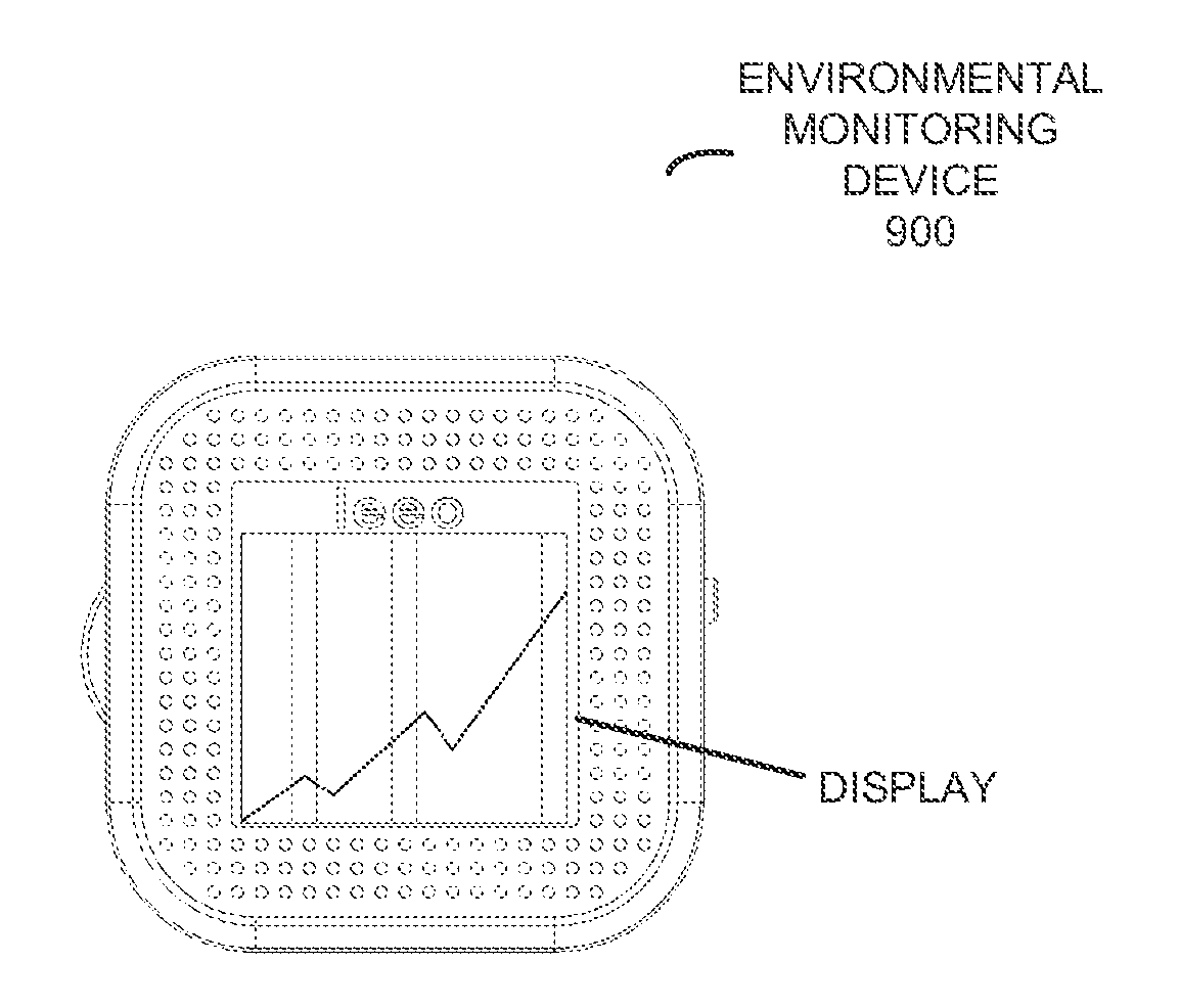
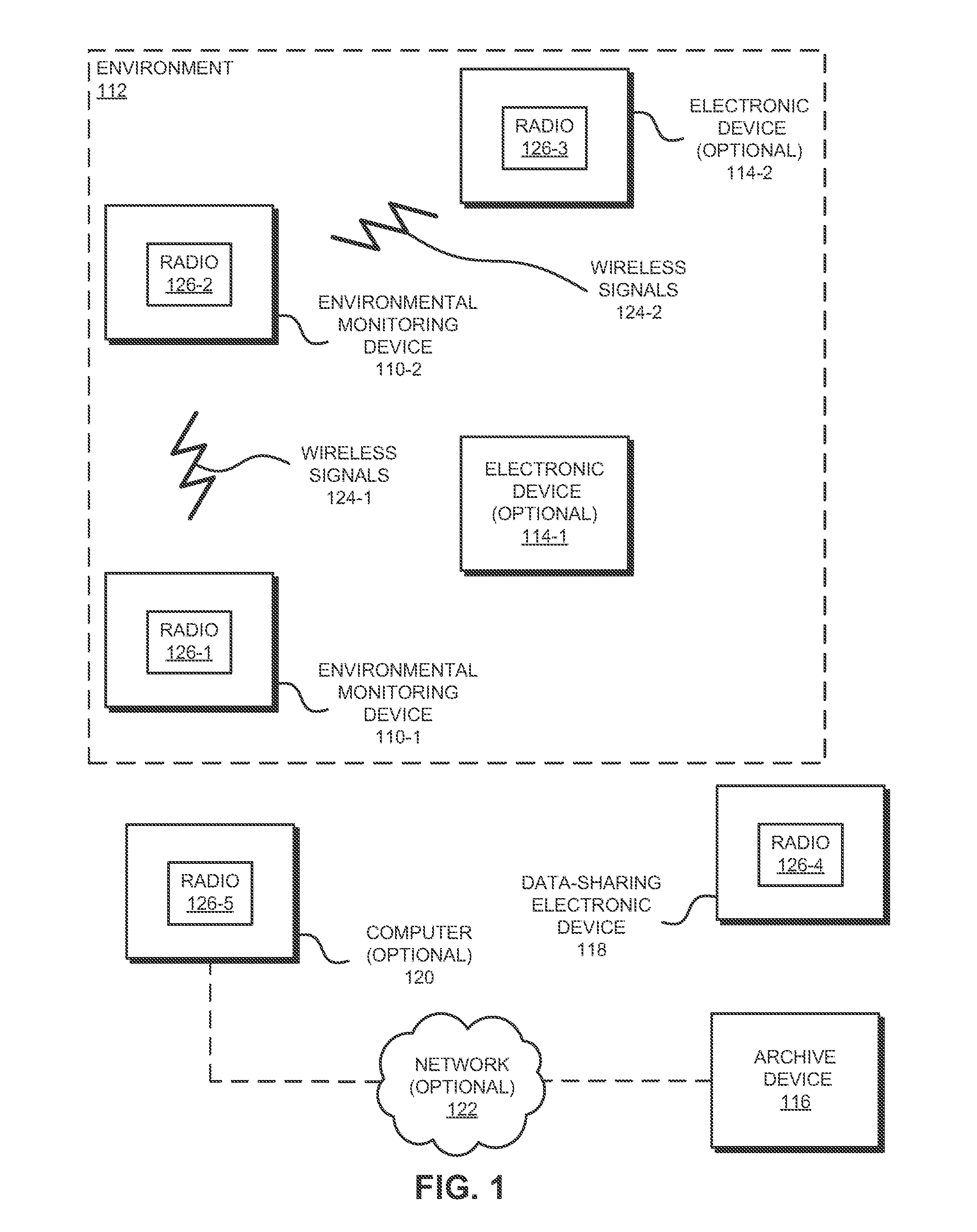
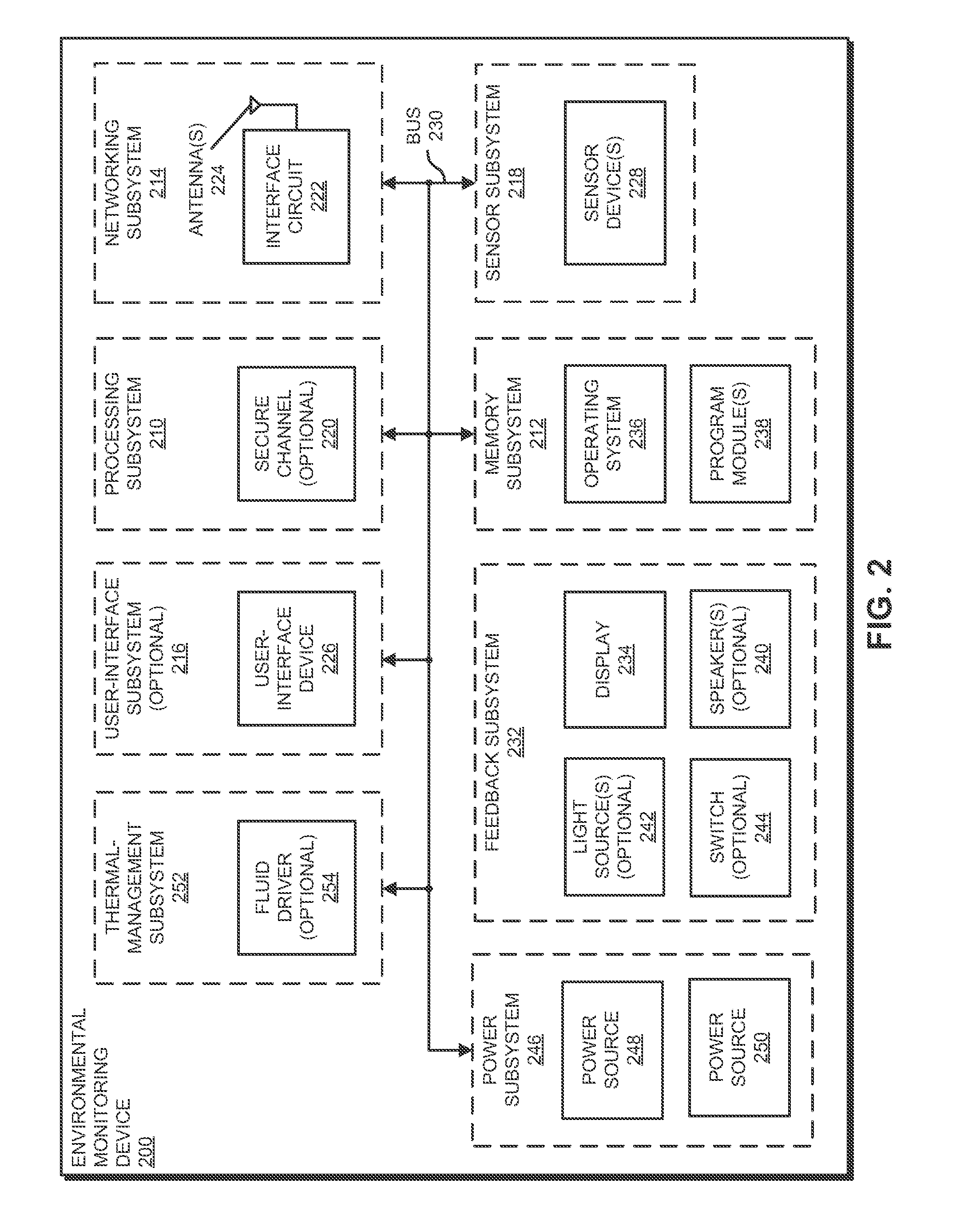
[0049]An environmental monitoring device that includes a sensor mechanism is described. During operation of the environmental monitoring device, heat generated by a processor in the environmental monitoring device may result in a convective fluid flow over the sensor mechanism that facilitates measurements of sensor data associated with an environmental condition in an external environment that includes the environmental monitoring device. Alternatively, a fluid driver (such as a fan) associated with the processor may produce the fluid flow over the sensor mechanism. Note that the fluid flow may include an airflow and / or a liquid flow. Moreover, the environmental monitoring device may include baffles that direct the fluid flow over a selected sensor in a set of sensors in the sensor mechanism.

[0050]In this way, the environmental monitoring device may facilitate low-power and / or low-cost measurements of the environmental condition. These capabilities promote sales of the environmenta...


PUM

PropertyMeasurementUnit
wavelengthsaaaaaaaaaa
concentrationaaaaaaaaaa

Abstract

An environmental monitoring device that includes a sensor mechanism is described. During operation of the environmental monitoring device, heat generated by a processor in the environmental monitoring device may result in a convective fluid flow over the sensor mechanism that facilitates measurements of sensor data associated with an environmental condition in an external environment that includes the environmental monitoring device. Alternatively, a fluid driver (such as a fan) associated with the processor may produce the fluid flow over the sensor mechanism. Note that the fluid flow may include an airflow and/or a liquid flow. Moreover, the environmental monitoring device may include baffles that direct the fluid flow over a selected sensor in a set of sensors in the sensor mechanism.

Description

CROSS REFERENCE TO RELATED APPLICATION[0001]This application claims priority under 35 U.S.C. §119(e) to: U.S. Provisional Application Ser. No. 61 / 847,079, entitled “Lighting Device with Environmental Monitoring System,” by Adam M. Gettings, Eddy Y. Chan, Andrew G. Stevens, and Bjorn H. Hovland, Attorney docket number LEEO-02, filed on Jul. 16, 2013; U.S. Provisional Application Ser. No. 61 / 847,555, entitled “Safety Detector with Environmental Monitoring System,” by Adam M. Gettings, Eddy Y. Chan, Andrew G. Stevens, and Bjorn H. Hovland, Attorney docket number LEEO-03, filed on Jul. 17, 2013; and U.S. Provisional Application Ser. No. 61 / 858,563, entitled “Switch with Environmental Monitoring System,” by Adam M. Gettings. Eddy Y. Chan, Andrew G. Stevens, and Bjorn H. Hovland, Attorney docket number LEEO-04, filed on Jul. 25, 2013, the contents of all of which are herein incorporated by reference.BACKGROUND[0002]1. Field[0003]The described embodiments relate generally to an environment...

Claims


Application Information

Patent Timeline
Patent Type & Authority Applications(United States)
IPC IPC(8): G01N33/00G01D7/00
CPCG01D7/00G01N33/00G08B21/18G01D11/245G01F1/00G01J1/0437G01J1/42G01N21/84G01N33/0031G08B3/00G08B3/10G08B13/02G08B17/10G08B19/005G08B21/12G08B29/181H01R13/6205H01R13/627G08B21/14G08B17/113G01N33/0075
Inventor GETTINGS, ADAM MATTHEWSTEVENS, ANDREW GETTINGSHOVLAND, BJORN
Owner LEEO
Why Eureka
Try Eureka