Thermal energy harvesting optimisation with bistable elements and collaborative behavior

a technology of bistable elements and thermal energy harvesting, applied in the manufacture/assembly of piezoelectric/electrostrictive devices, transducer types, electrical apparatuses, etc., can solve problems such as unoptimized energy recovery

Active Publication Date: 2015-01-22
COMMISSARIAT A LENERGIE ATOMIQUE ET AUX ENERGIES ALTERNATIVES +1
View PDF5 Cites 3 Cited by
  • Summary
  • Abstract
  • Description
  • Claims
  • Application Information

AI Technical Summary

Problems solved by technology

The energy transmitted to the piezoelectric material

Method used


Image

  • Thermal energy harvesting optimisation with bistable elements and collaborative behavior
  • Thermal energy harvesting optimisation with bistable elements and collaborative behavior
  • Thermal energy harvesting optimisation with bistable elements and collaborative behavior

Examples


Embodiment Construction

[0006]The purpose of this invention is to offer a system for converting thermal energy into electrical energy with improved efficiency.

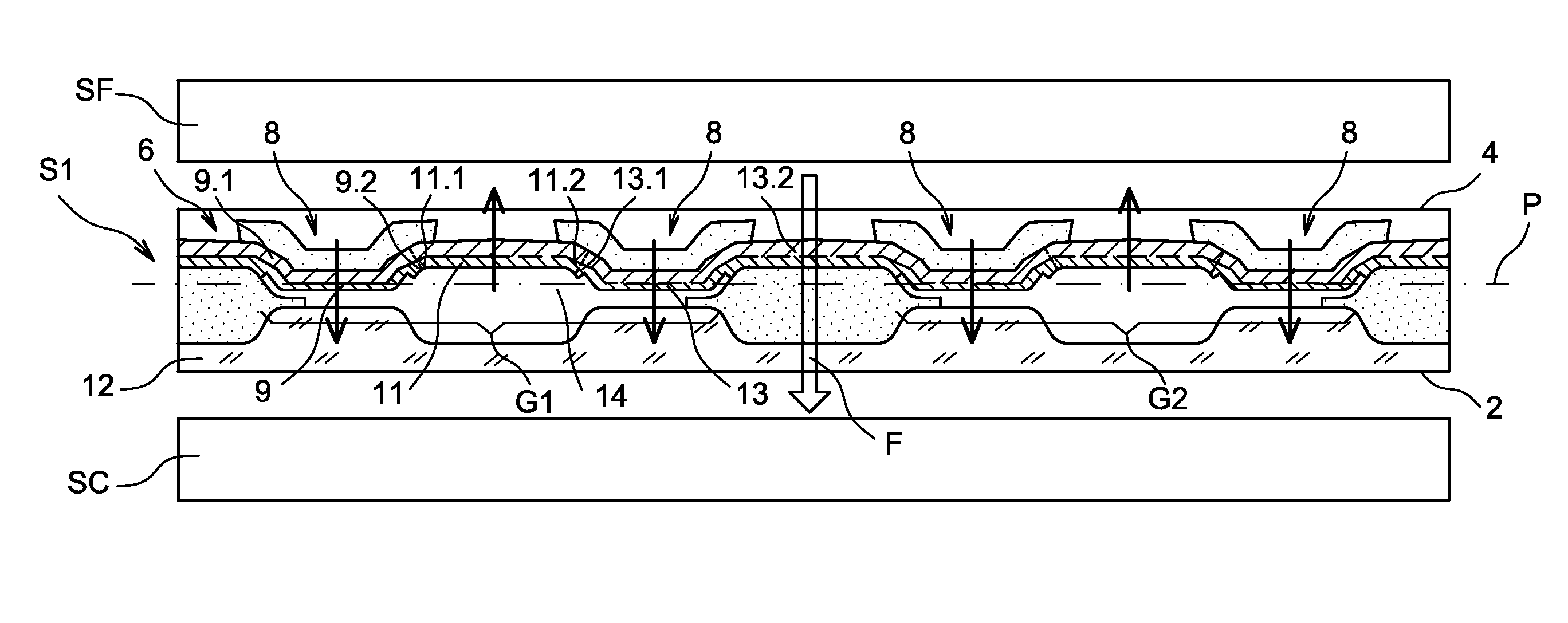
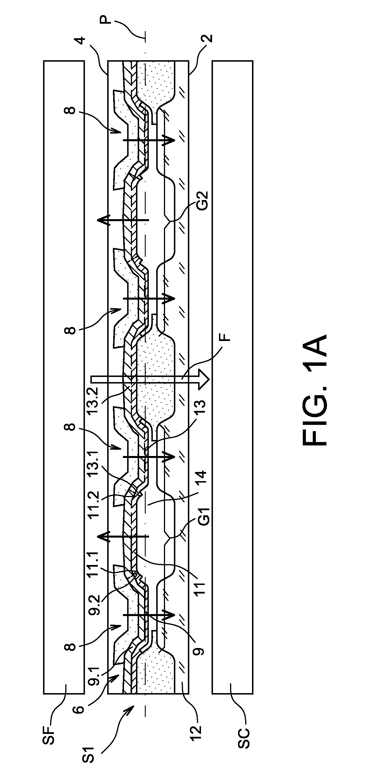
[0007]The purpose mentioned hereinabove is achieved by a system for converting thermal energy into electrical energy comprising a transducer of mechanical energy into electrical energy and at least one convertor of thermal energy into mechanical energy, with the convertor comprising at least two preformed bimetallic strips linked mechanically in series and having opposite and controlled curvatures. The bimetallic strips can be manufactured from a single piece.

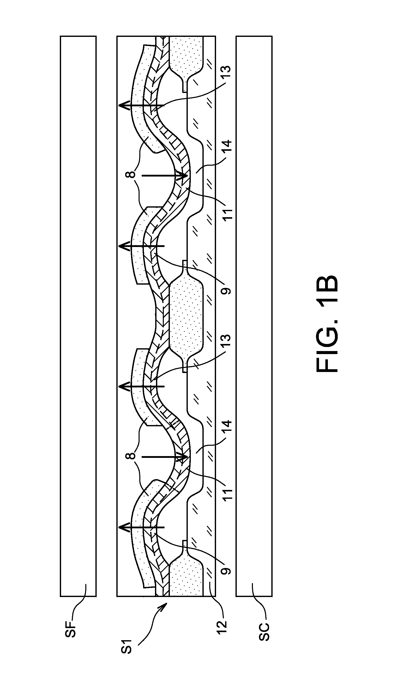
[0008]In other terms, preformed bimetallic strips are associated in opposition in such a way that the blistering of one participates in the unblistering of the other, as such reducing the energy required for the blistering or unblistering of each of the bimetallic strips, as such increasing the switching frequency of each of the bimetallic strips.

[0009]The bimetallic strips operate in a collabor...


PUM

PropertyMeasurementUnit
Energyaaaaaaaaaa
Piezoelectricityaaaaaaaaaa
Mechanical energyaaaaaaaaaa

Abstract

System for converting thermal energy into electrical energy (S1) intended to be arranged between a hot source (SC) and a cold source (SF), comprising means for converting thermal energy into mechanical energy (6) and a piezoelectric material, with the means for converting thermal energy into mechanical energy (6) comprising groups (G1, G2) of at least three bimetallic strips (9, 11, 13) linked mechanically together by their longitudinal ends and suspended above a substrate (12), each bimetallic strip (9, 11, 13) comprising two stable states wherein it has in each of the states a curvature, with two directly adjacent bimetallic strips (9, 11, 13) having for a given temperature opposite curvatures, with the switching from one stable state of the bimetallic strips (9, 11, 13) to the other causing the deformation of a piezoelectric material.

Description

TECHNICAL FIELD AND PRIOR ART[0001]This invention provides a system for converting thermal energy into electrical energy.[0002]Electronic circuits, when they are operating, produce heat. This heat is not used and must be removed in order to avoid deteriorating the circuits. Other sources of heat are also present in our environment, such as for example conduits, exhaust, the walls of industrial machines, etc., of which the heat given off is not used.[0003]It is considered to recover this heat in order to convert it into electrical energy.[0004]It is for example considered to use bimetallic strips, the latter are formed of two strips of different metals, materials or alloys with different coefficients of expansion, flexible, welded or glued to one another, in the lengthwise direction. Due to the different coefficients of expansion of the two strips, the bimetallic strip are deformed with a large amplitude when it is heated as well as when it is cooled. When it is heated, the latter sw...

Claims


Application Information

Patent Timeline
IPC IPC(8): H02N2/18
CPCH02N2/18H02N2/186Y10T29/42
Inventor MONFRAY, STEPHANESAVELLI, GUILLAUMESKOTNICKI, THOMASCORONEL, PHILIPPEGAILLARD, FREDERIC
Owner COMMISSARIAT A LENERGIE ATOMIQUE ET AUX ENERGIES ALTERNATIVES
Why Eureka
Try Eureka