

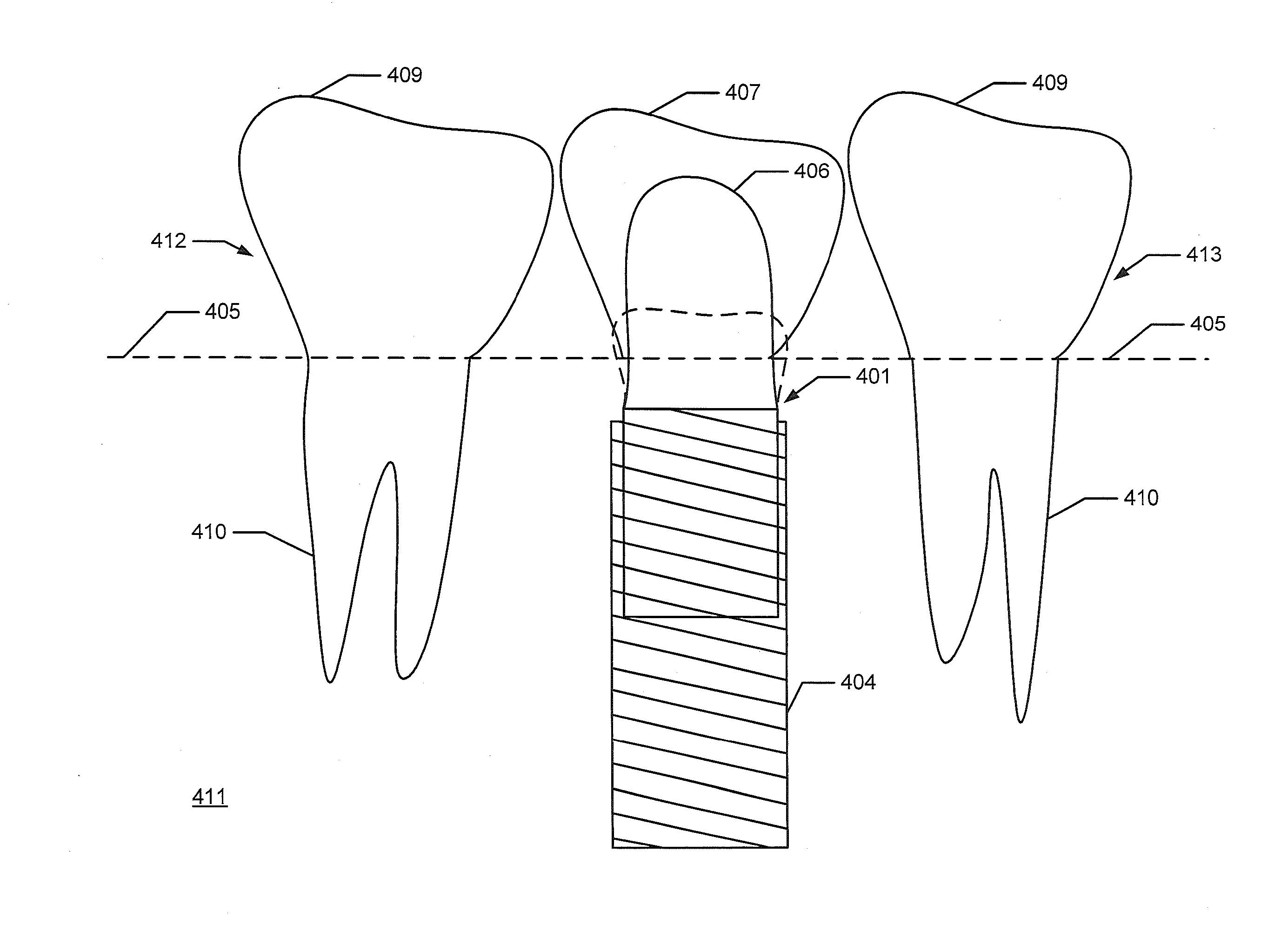
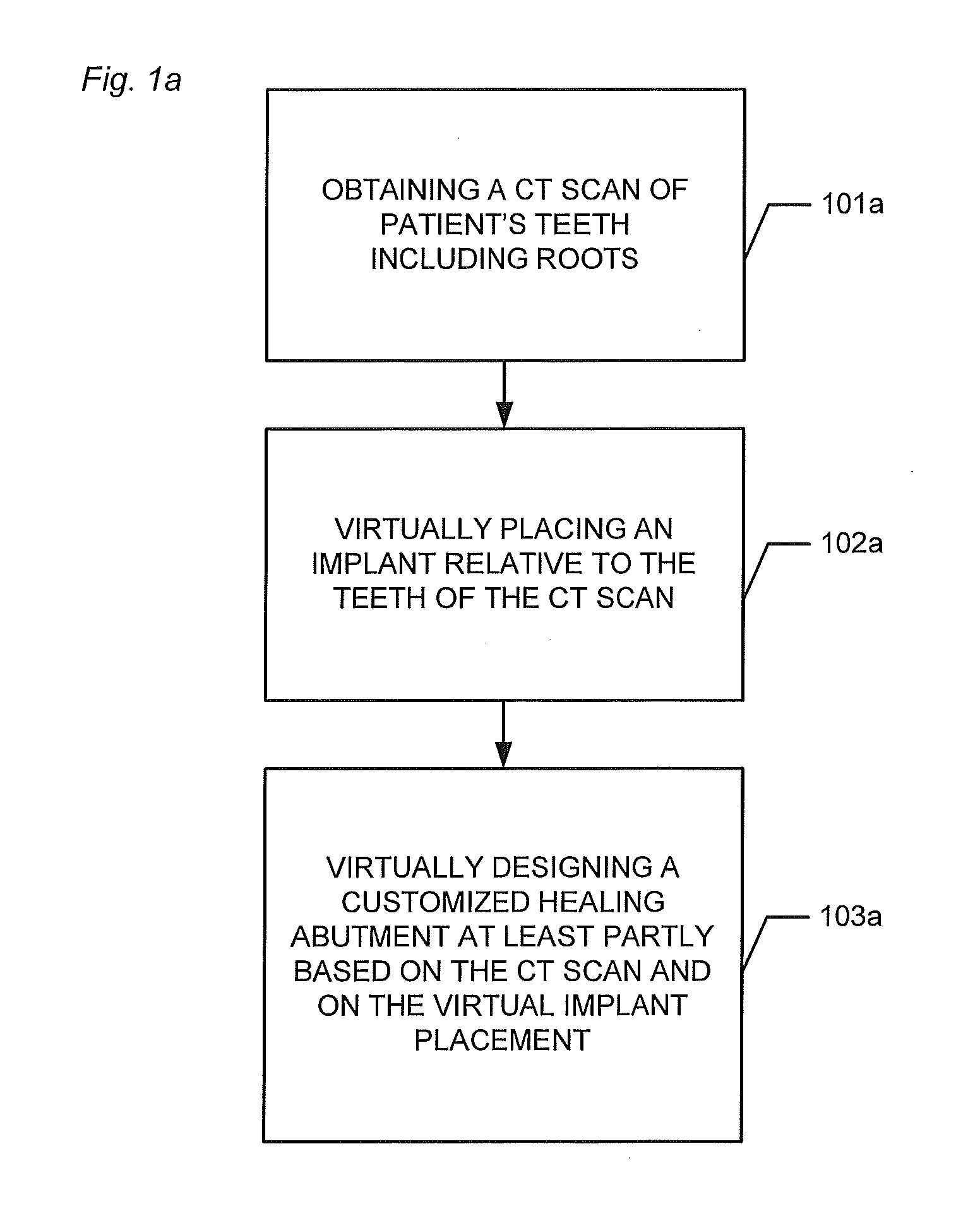
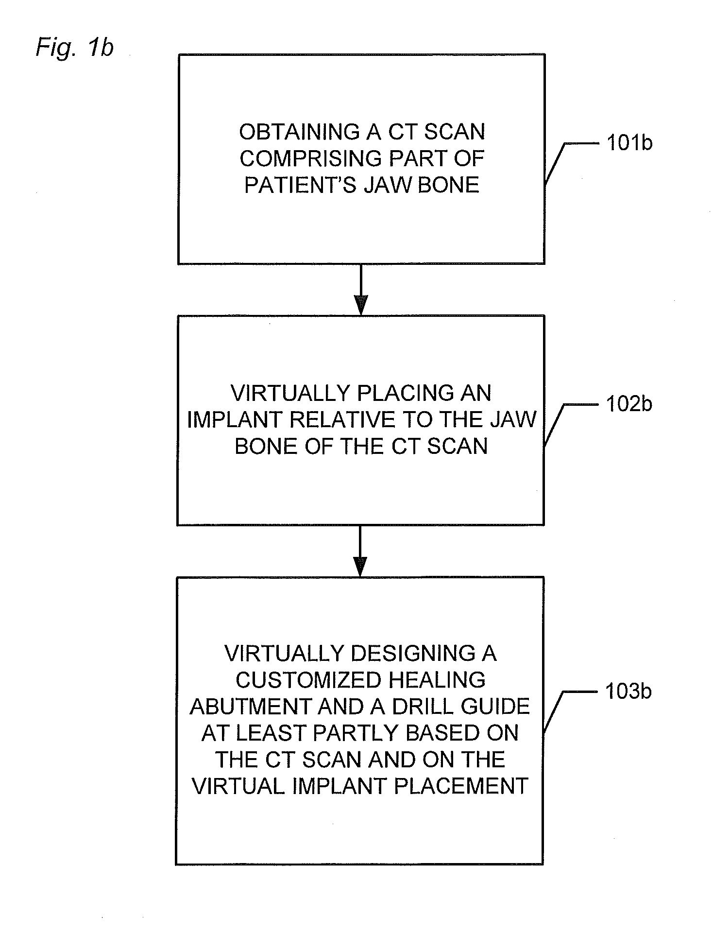
Virtually designing a customized healing abutment
a technology of customized healing and abutments, which is applied in the field of virtual design of customized healing abutments for patients, can solve the problems of significant additional discomfort, inability to arrange implants in the patient's jaw bone, and the subsequent design of drill guides and customized healing abutments
- Summary
- Abstract
- Description
- Claims
- Application Information
AI Technical Summary
Benefits of technology
Problems solved by technology
Method used
Image

Examples
embodiment 1
2. The method , wherein the method comprises obtaining a 3D surface scan comprising at least part of the teeth and at least part of the soft tissue of the patient's mouth.
3. The method according to any one or more of the preceding embodiments, wherein the method comprises performing an alignment of the CT scan and the 3D surface scan before designing the customized healing abutment and the drill guide.
4. The method according to any one or more of the preceding embodiments, wherein the alignment comprises selecting three corresponding points on the CT scan and on the 3D surface scan.
5. The method according to any one or more of the preceding embodiments, wherein the alignment comprises using the computer-implemented method of iterative closets point.
6. The method according to any one or more of the preceding embodiments, wherein the drill guide and the customized healing abutment are designed simultaneously.
7. The method according to any one or more of the preceding embodiments, wher...
embodiment 56
57. The user interface , wherein the user interface is configured for obtaining and visualizing a 3D surface scan comprising at least part of the teeth and soft tissue of the patient's mouth.
58. The user interface according to embodiment 56 or 57, wherein the user interface is configured for performing an alignment of the CT scan and the 3D surface scan before designing the customized healing abutment and the drill guide.
59. The user interface according to any of embodiments 56 to 58, wherein the user interface is configured for virtually placing a final restoration for the implant relative to the CT scan and / or relative to the 3D surface scan, and for virtually designing the final restoration.
60. The user interface according to any of embodiments 56 to 59, wherein the user interface is configured for virtually placing the final restoration before virtually placing the implant.
61. The user interface according to any of embodiments 56 to 60, wherein the user interface is configured f...
PUM
 Abstract
Description
Claims
Application Information