Lace Fitting Structure

a technology of lace fitting and structure, which is applied in the direction of shoe lace fastening, footwear, fastening, etc., can solve the problems of insufficient fit of the upper and the foot in the area, and achieve the effect of avoiding local tightening

Active Publication Date: 2015-01-29
ASICS CORP
View PDF3 Cites 26 Cited by
  • Summary
  • Abstract
  • Description
  • Claims
  • Application Information

AI Technical Summary

Benefits of technology

[0017]According to the present invention, lacing apertures for passing the second shoelace means therethrough are formed by exposed areas of the first shoelace means, and since the length of the exposed area in the longitudinal direction is greater than the width or the thickness of the second shoelace means, the engagement position at which the second shoelace means engages with the first shoelace means can be displaced in the longitudinal direction. This makes it possible to accommodate changes of the shape of the foot following changes of the foot shape and the posture of the wearer, and the upper is likely to fit to the foot with a uniform pressure, avoiding local tightening.

Problems solved by technology

In the shoe of the first patent document, a plurality of loop members for passing a shoelace therethrough are fixed to the upper end of the sole, and the sole is likely to fit to the sole of the foot, but the upper will not sufficiently fit to the foot.
In the shoe of the first patent document, a plurality of loops for passing a shoelace therethrough are passing around the back surface of the heel, and therefore the heel portion of the upper is likely to fit to the foot, but the upper will not sufficiently fit to the foot in the area anterior to the top-line (mouth).

Method used


Image

  • Lace Fitting Structure
  • Lace Fitting Structure
  • Lace Fitting Structure

Examples


embodiment 1

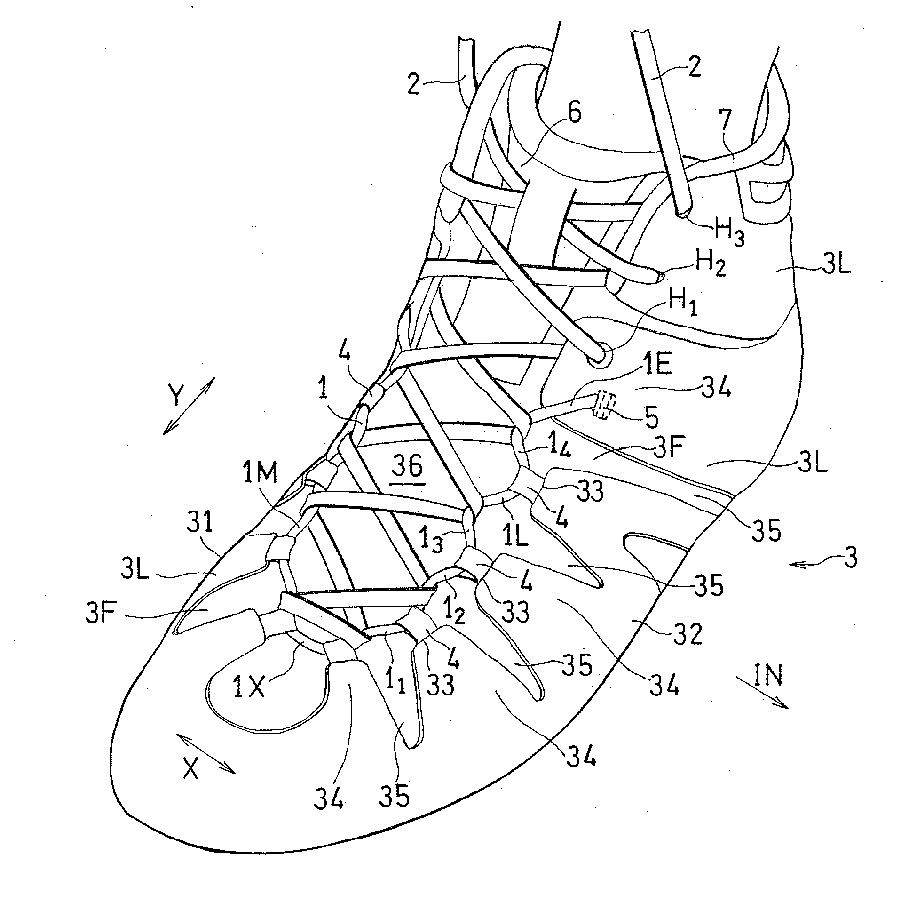
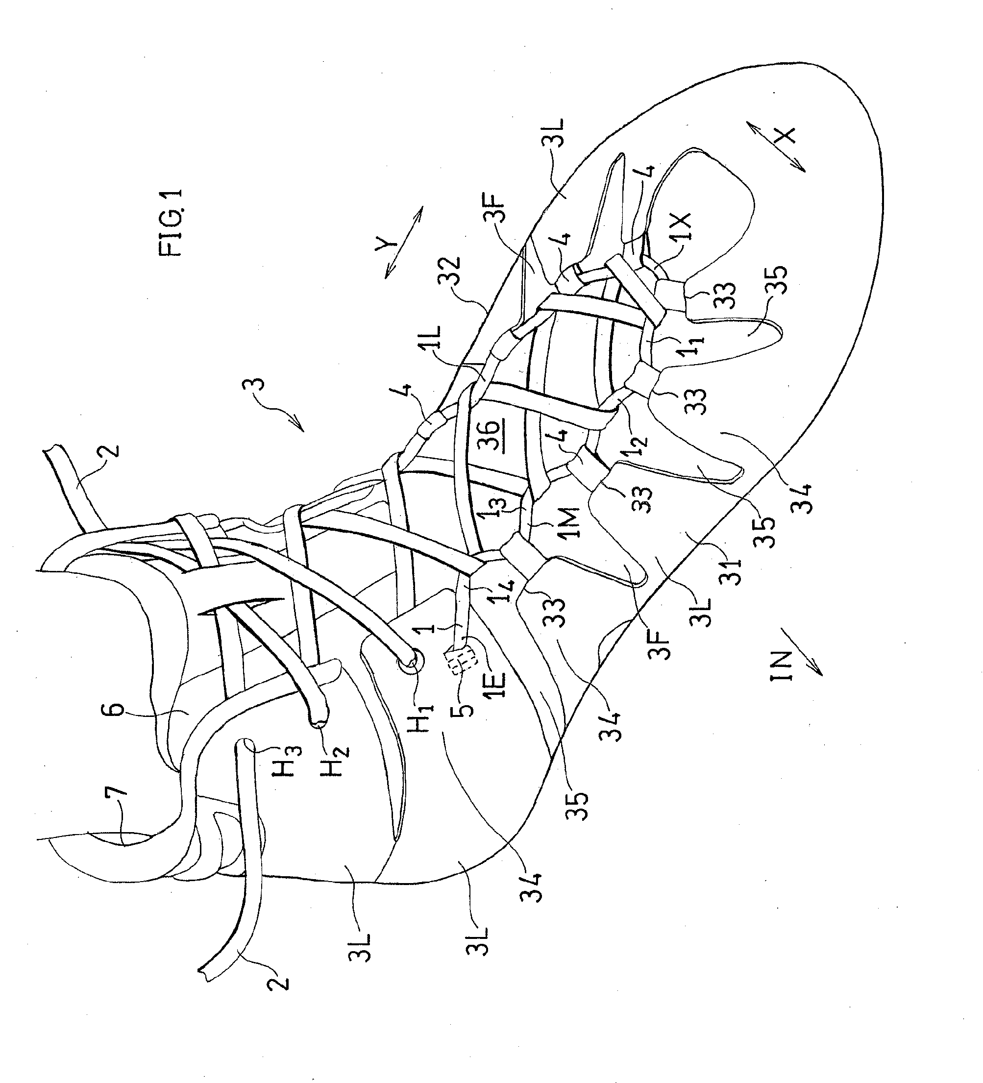
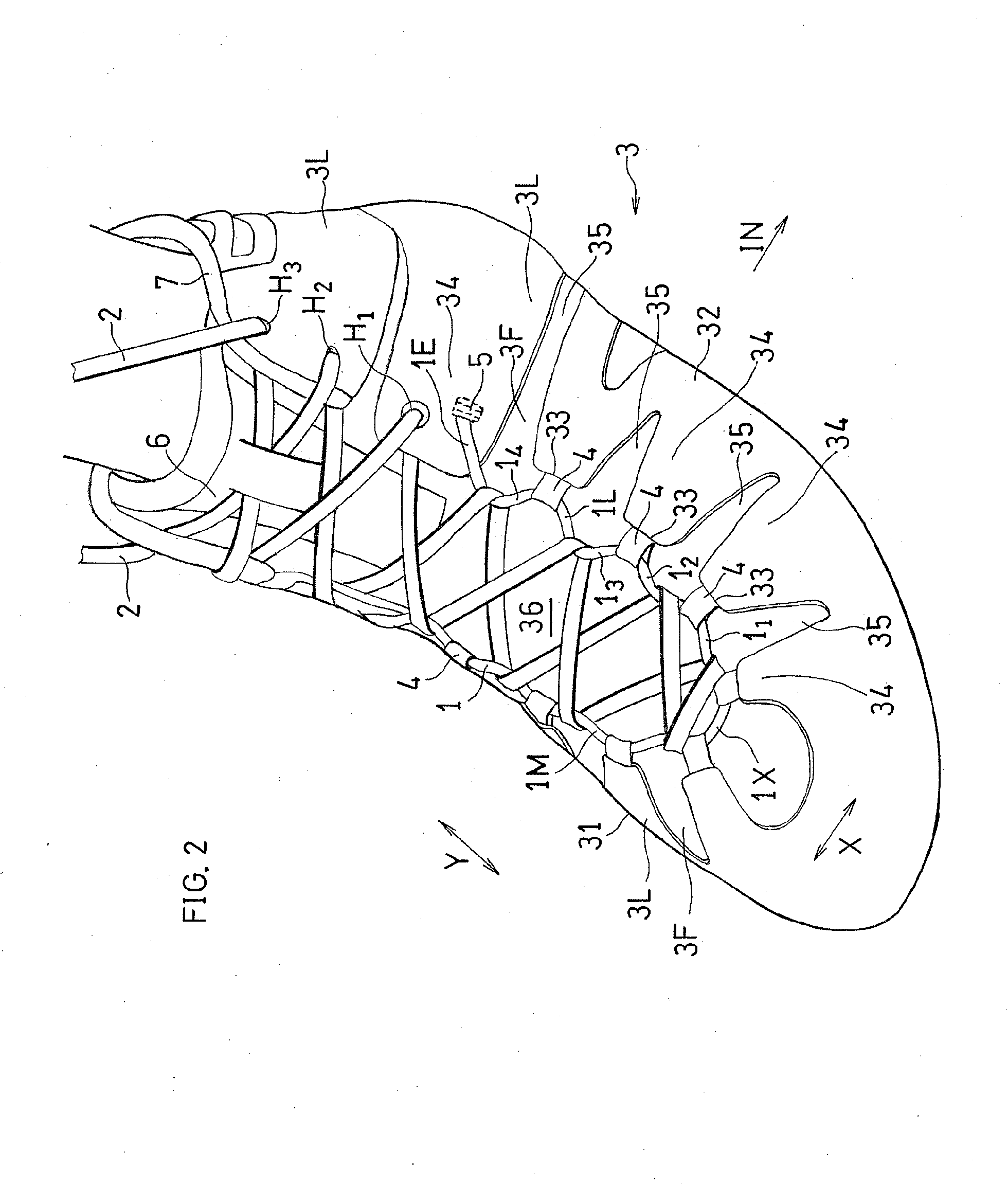
[0085 of the present invention will now be described with reference to FIGS. 1 to 6B.

[0086]An upper for the left foot will be illustrated in the following description. In the following figures, the arrow OUT represents the lateral side direction of the foot, and the arrow IN represents the medial side direction of the foot.

[0087]A shoe having a lace fitting structure shown in FIG. 1 is for example a high-cut wrestling shoe, and includes a sole (not shown), an upper 3, and first and second shoe laces 1 and 2.

[0088]The sole is placed under the upper 3, and is to be in contact with the road surface. The upper 3 wraps around the instep of the foot, and includes a tongue 6. The shoelaces 1 and 2 are for fitting the upper 3 to the instep of the foot.

[0089]Although the opposite end portions of the second shoelace 2 are not shown in FIGS. 1 and 2, the opposite end portions are tightly tied together after the foot is inserted into the upper 3. As the end portions of the second shoelace 2 are...


PUM


Abstract

A lace fitting structure for fitting an upper 3 wrapping around an instep of a foot to the instep, the structure including: a medial side portion 31 covering the instep and a medial side surface of a big toe; a lateral side portion 32 covering the instep and a lateral side surface of a little toe; first shoelace means 1 placed to extend in a longitudinal direction Y of the foot and engaged with the medial side portion 31 and the lateral side portion 32 along central edge portions 33 of the medial side portion 31 and the lateral side portion 32; placement means for placing a portion of the first shoelace means 1 so that the first shoelace means 1 is exposed in a plurality of exposed areas 1i, which are separated from one another in the longitudinal direction Y; and second shoelace means 2 engaging, in a transverse direction X of the foot, with the first shoelace means 1 in the plurality of exposed areas 1i so as to bring the medial side portion 31 and the lateral side portion 32 closer to each other, wherein a length L of the exposed areas 1i in the longitudinal direction Y is greater than a thickness and a width of the second shoelace means 2.

Description

TECHNICAL FIELD[0001]The present invention relates to a shoe having a lace fitting structure.BACKGROUND ART[0002]A shoelace fits an upper to the foot. The upper, fitted to the foot, supports the foot.[0003]However, when the MP joint is dorsiflexed, the shape of the foot changes, thereby also changing the foot circumference. When a shoe is worn over a long time, the foot circumference often increases. In such a case, the foot in the shoe will be compressed by the upper. Also, slippage often occurs between the shoe and the foot during movement.[0004]Particularly, the middle foot section of the foot substantially changes its shape as the posture changes. If the upper, which is fitted to the foot when standing still, fails to follow changes of the shape of the foot, the fit between the upper and the foot significantly deteriorates during movement.CITATION LISTPatent Literature[0005]First Patent Document: JP2005-13365A (Abstract)[0006]Second Patent Document: JP2001-46103A (Abstract)SUMMA...

Claims


Application Information

Patent Timeline
Patent Type & Authority Applications(United States)
IPC IPC(8): A43C11/22A43C1/02A43C1/04A43C5/00A43C1/00
CPCA43C11/22A43C5/00A43C1/02A43C1/04A43C1/006A43C1/06A43C1/00A43C1/003Y10T24/3737Y10T24/3742Y10T24/3787
Inventor NONOGAWA, MAINAKANISHI, KEIZO
Owner ASICS CORP
Why Eureka
Try Eureka