Pipe support structure

a support structure and pipe technology, applied in the direction of clutches, mechanical devices, manufacturing tools, etc., can solve the problems of reducing the rigidity of the resin pipe, deteriorating the responsive property, and possibly giving rise to vibration in the hydraulic pressure, etc., to suppress the compliance amount of the hose, the effect of low cost and simple construction

Inactive Publication Date: 2015-01-29
TOYOTA JIDOSHA KK
View PDF0 Cites 0 Cited by
  • Summary
  • Abstract
  • Description
  • Claims
  • Application Information

AI Technical Summary

Benefits of technology

[0018]The present invention is made for solving the conventional problem previously mentioned, and has an object to provide a pipe support structure which can be realized with a simple construction and a low cost for suppressing the hose compliance amount in a high temperature area while maintaining the degree of freedom in mountability inherent to the resin pipe by utilizing the Coriolis force and the reaction force caused on the pipe.

Problems solved by technology

This results in the fact that the hydraulic pressure in the resin pipe 103 is decreased, thereby causing such a problem that the hydraulic machine such as the gear shift actuator 102 and the like among other things deteriorates in responsive property.
Further, the abruptly lowering in rigidity of the resin pipe 103 possibly gives rise to vibrations in the hydraulic pressure.

Method used


Image

  • Pipe support structure
  • Pipe support structure
  • Pipe support structure

Examples


Embodiment Construction

[0045]The embodiment of the present invention will be explained hereinafter with reference to the accompanying drawings.

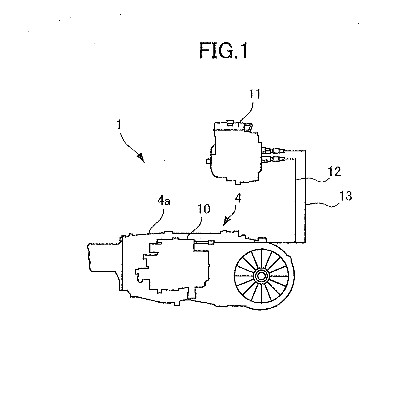
[0046]Referring to FIG. 1, explanation will be made about a vehicle 1 to which the pipe support structure according to the present embodiment of the present invention is applied. Firstly, the construction of this embodiment will be explained.

[0047]As shown in FIG. 1, the vehicle 1 is constructed to include an engine not shown serving as a drive source, a clutch mechanism also not shown, and an AMT (Automated Manual Transmission) 4. The clutch mechanism and the AMT 4 are drivably connected with each other by torque tube also not shown.

[0048]The engine is constructed by a known drive unit which is adapted to output a drive force by burning a mixture of air and fuel including gasoline, light oil and other hydrocarbon fuels in combustion chambers each formed by a cylinder not shown. The engine is constructed to be operated by repeatedly performing a series of steps inc...


PUM

PropertyMeasurementUnit
temperatureaaaaaaaaaa
attenuation coefficientaaaaaaaaaa
forceaaaaaaaaaa

Abstract

A pipe support structure which is constructed to utilize the Coriolis force and the reaction force caused, thereby making it possible to suppress the hose compliance amount in the high temperature area while maintaining the degree of freedom of mountability specific for the resin pipe and to realize the above suppressing effect by the simple construction and at a low cost.

Description

[0001]This is a Continuation of application Ser. No. 13 / 392,203 filed Feb. 24, 2012, which is a National Stage of Application No. PCT / JP2011 / 004612 filed Aug. 18, 2011 which claims priority to Japanese Patent Application No. 2010-223997 filed Oct. 1, 2010. The prior applications, including the specifications, drawings and abstract are incorporated herein by reference in their entirety.FIELD OF INVENTION[0002]The present invention relates to a pipe support structure, and more particularly to a pipe support structure for allowing a high temperature fluid to pass therethrough.BACKGROUND OF INVENTION[0003]In general, a hydraulic machine such as an actuator and the like to be hydraulically driven and controlled is supplied with working oil through pipes. The actuator of this type to be hydraulically driven and controlled is for example mounted on a vehicle like an automotive vehicle, and thus utilized for controlling a wide variety of drive units provided on the vehicle.[0004]As an appar...

Claims


Application Information

Patent Timeline
Patent Type & Authority Applications(United States)
IPC IPC(8): F16L3/16F16L11/08
CPCF16L11/08F16L3/16F16L55/035F16D2048/0224Y10T29/49959
Inventor MIKI, HIRONORI
Owner TOYOTA JIDOSHA KK
Why Eureka
Try Eureka