Switch

a technology of switches and switches, applied in the field of switches, can solve the problems of increasing the thickness of the contact structure and the difficulty of reducing the thickness of the product, and achieve the effect of small switch size and thinner switch

Active Publication Date: 2015-01-29
ORMON CORP
View PDF4 Cites 3 Cited by
  • Summary
  • Abstract
  • Description
  • Claims
  • Application Information

AI Technical Summary

Benefits of technology

[0007]The arms of the movable contacts in the switch, however, are extended obliquely downward from the bottom surface of the slider, increasing the thickness of a contact structure, which renders it difficult to reduce the thickness of the product. Additionally, the switch requires the housing, movable holder or slider, movable contact member, and spring members in order to provide the clicking feeling to the switch, which needs a considerably number of components.
[0008]One or more embodiments of the present invention reduces the thickness of the switch and its number of components while maintaining the click feeling.

Problems solved by technology

The arms of the movable contacts in the switch, however, are extended obliquely downward from the bottom surface of the slider, increasing the thickness of a contact structure, which renders it difficult to reduce the thickness of the product.

Method used


Image

  • Switch
  • Switch
  • Switch

Examples


first embodiment

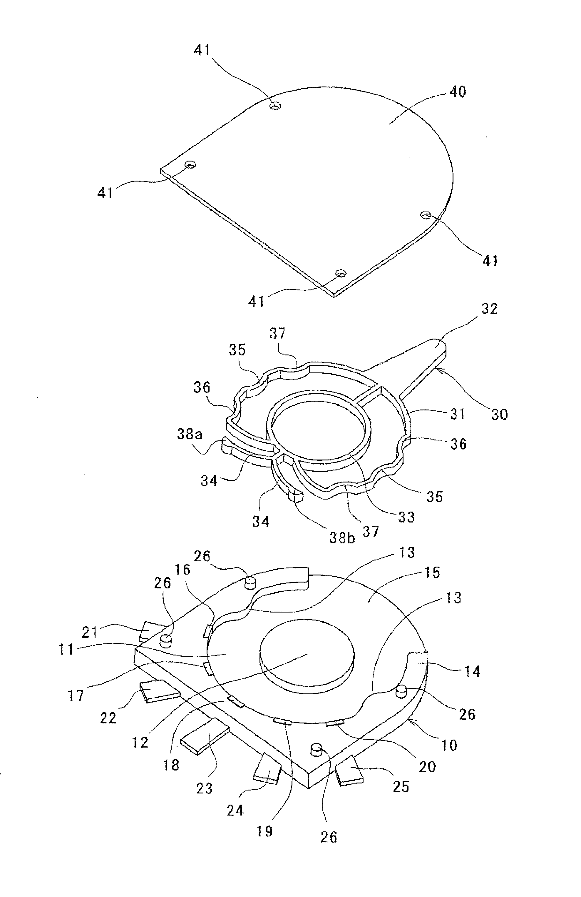
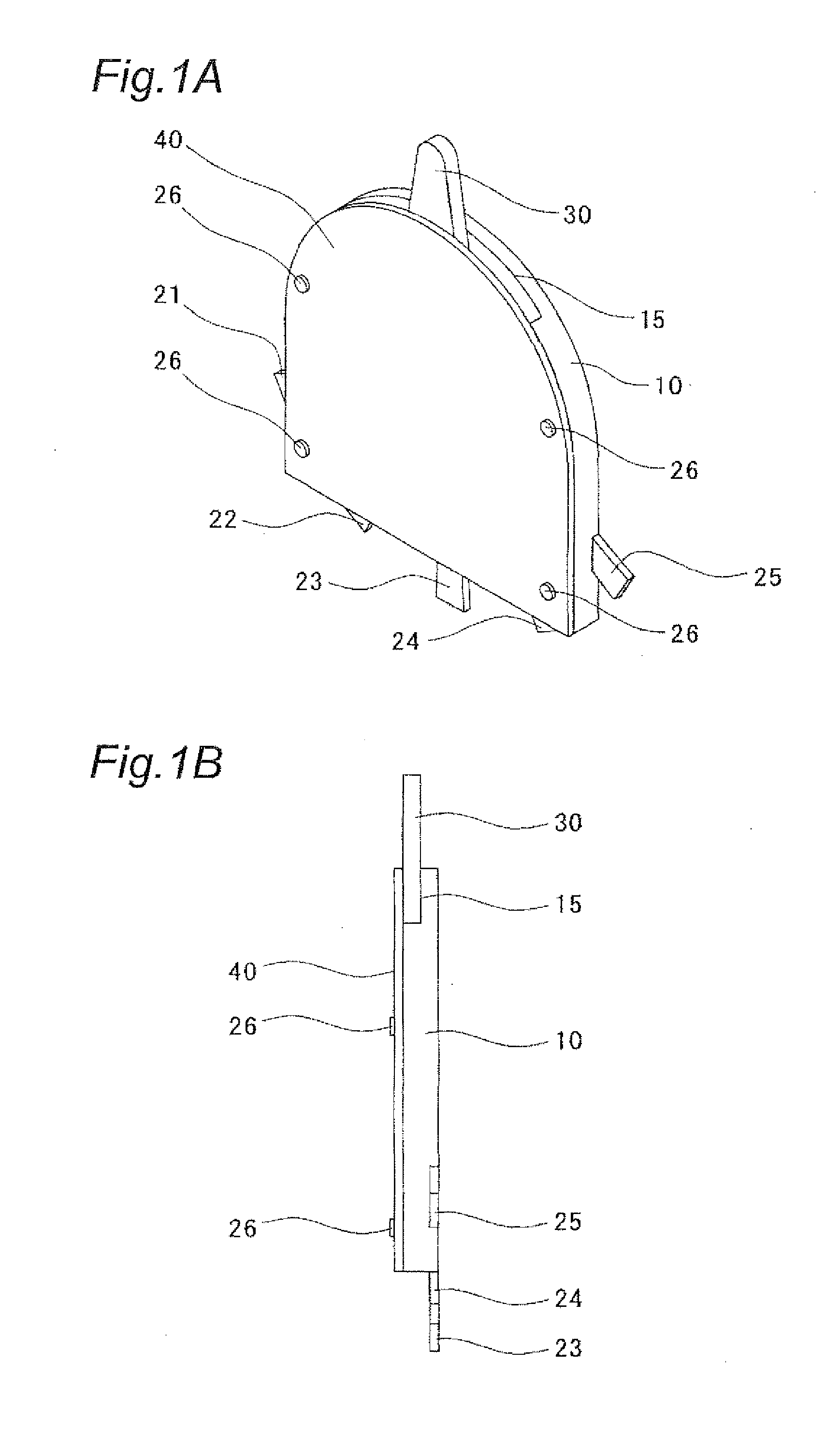
[0049]As illustrated in FIGS. 1A to 4B, the switch according to the first embodiment includes a base 10, an actuator 30, and a cover 40.

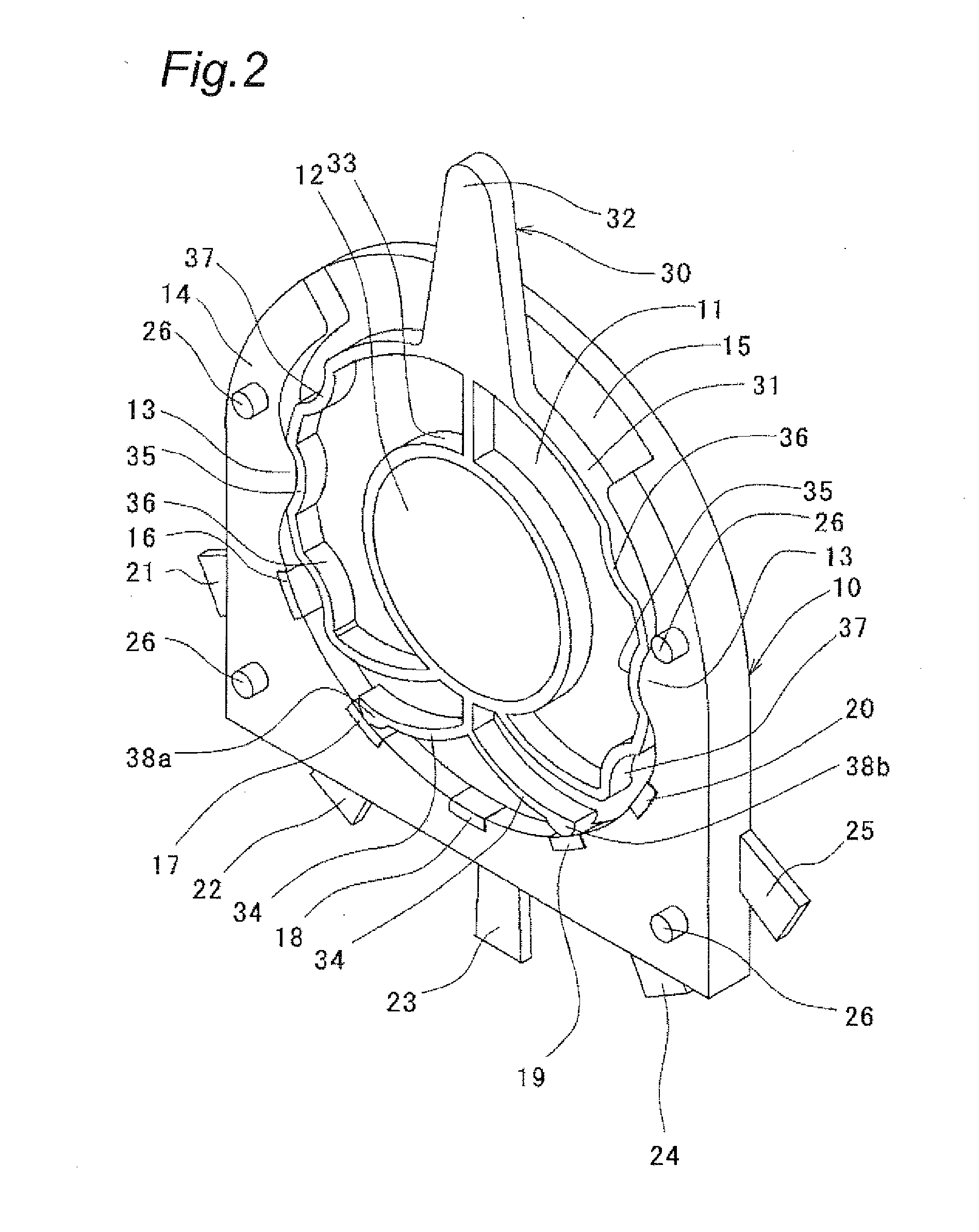
[0050]As illustrated in FIG. 3, the base 10 has a fitting recess (hereinafter, referred to as “recess”) 11 defined therein, in which the actuator 30 described below is fitted on its upper surface. The recess 11 has a shaft or boss 12 defined at its center for supporting an engaging portion 33 of actuator 30 described below. The opposing side surfaces defining in part the recess 11 have engagement concave portions 13 for engagement with associated engagement convex portions 35, 36, and 37 of the actuator 30 described below.

[0051]An outer peripheral wall 14 forming the recess 11 has an operational cutout or opening 15 defined by removing an upper part thereof indicated in FIGS. 1A and 1B. The opposite ends of the peripheral wall 14 are designed so that the arms 32 of the actuator 30 make contacts therewith when the switch takes the second and third po...

second embodiment

[0070]As illustrated in FIGS. 6A to 9B, the switch according to the second embodiment includes a base 50, an actuator 70, and a cover 90. The terminologies “up,”“down,”“left,” and “right” below are used for convenience in describing the switch with reference to the drawings, which does not intend to limit the arrangement of the switch.

[0071]As illustrated in FIG. 8, the base 50 has a substantially rectangular recess (hereinafter, referred to as “recess”) 51 defined thereon for accommodating the actuator 70 described below on the upper surface thereof, forming a peripheral wall defining thereinside the recess 51. The peripheral wall, which has a cutout or opening 52 defined at the center of one of its longitudinally extending portions, includes upper peripheral portions 53 positioned on either side of the operational opening 52, a lower peripheral portion 54 opposing the upper peripheral portions 53, and left and right peripheral portions 55 and 56 connecting between the upper and lo...

third embodiment

[0088]FIG. 10 illustrates a switch of the third embodiment of the present invention. This switch is substantially similar to the second embodiment, but it is different from that in that the actuator in the second position is maintained in its position while the actuator in the third position is automatically returned to the first position. In the third embodiment, like reference numerals designate like components in the second embodiment to the descriptions thereto will be omitted.

[0089]As illustrated in FIG. 10, the elastic engagement portion 73 of the switch has the narrowing portion 76, the second engagement recessed portion 77 on one side of the first engagement recessed portion 75, and an elastic inclined portion (elastic portion) 81 on the other side of the first engagement recessed portion 75. The elastic inclined portion 81 is formed like “S” inclined toward right. One end of the “S” shaped, elastic inclined portion is connected to the first engagement recessed portion 75, a...


PUM


Abstract

A switch has a base having a recess, and a plurality of fixed contacts mounted in an inner side face of the recess, an electrically conductive actuator disposed within the recess of the base, the electrically conductive actuator having a pair of movable contact portions and an elastically deformable elastic portion, the movable contact portions having movable contacts capable of being connected to respective fixed contacts, at least one engagement convex portion disposed on one of the base and the electrically conductive actuator, and at least one engagement concave portion disposed on the other of the base and the electrically conductive actuator and engageable with the at least one engagement convex portion. The elastic portion of the electrically conductive actuator is elastically deformed to break an engagement between the engagement convex and concave portions when the actuator moves between a first position and a second position.

Description

BACKGROUND[0001]1. Technical Field[0002]The present invention relates to a switch capable of providing a click feeling. In particular, the present invention relates to an ultra-compact and thin switch with minimum number of components, for use with electronic device such as mobile phone, smartphone, or digital camera.[0003]2. Related Art[0004]Patent Document 1 discloses a slide switch. The slide switch includes a slider capable of reciprocating between two positions and having a step mounted on its side surface, a housing accommodating the slider and having fixed contacts mounted on the bottom surface and spaced apart from each other in the moving direction of the slider, a movable contact member having arms extending obliquely downward and capable of making contacts with the fixed contacts mounted on the housing, a clicking metallic spring disposed between the inner side surface of the housing and the side surface of the slider and having a protrusion mounted on one side opposing t...

Claims


Application Information

Patent Timeline
Patent Type & Authority Applications(United States)
IPC IPC(8): H01H1/36
CPCH01H1/36H01H2229/014H01H2221/044H01H2205/002H01H3/50H01H21/50H01H1/44H01H21/30H01H15/16
Inventor MORIMOTO, MASARUARIHARA, TAKESHIWASHIZU, TOMOYUKI
Owner ORMON CORP
Why Eureka
Try Eureka