Method for attaching crimping members, sheet binding device, and image forming apparatus

a technology of crimping members and attachment devices, which is applied in the direction of electrographic processes, instruments, manufacturing tools, etc., can solve the problems of failure to apply a stable binding for

Active Publication Date: 2015-01-29
RICOH KK
View PDF4 Cites 18 Cited by
  • Summary
  • Abstract
  • Description
  • Claims
  • Application Information

AI Technical Summary

Benefits of technology

[0010]It is an object of the present invention to at least partially solve the problems in the conventional technology.

Problems solved by technology

However, due to attachment errors of the crimping members and the accuracies of the members attached to the crimping members, etc., the crimping members may be attached in positions deviated from their original engagement position.
If the crimping members are attached in positions deviated from the original engagement positions in this way, the crimping members have a strongly-engaged portion and a weakly-engaged portion, thereby fail to apply a stable binding force.

Method used


Image

  • Method for attaching crimping members, sheet binding device, and image forming apparatus
  • Method for attaching crimping members, sheet binding device, and image forming apparatus
  • Method for attaching crimping members, sheet binding device, and image forming apparatus

Examples


Embodiment Construction

[0039]An exemplary embodiment of the present invention will be explained below with reference to accompanying drawings.

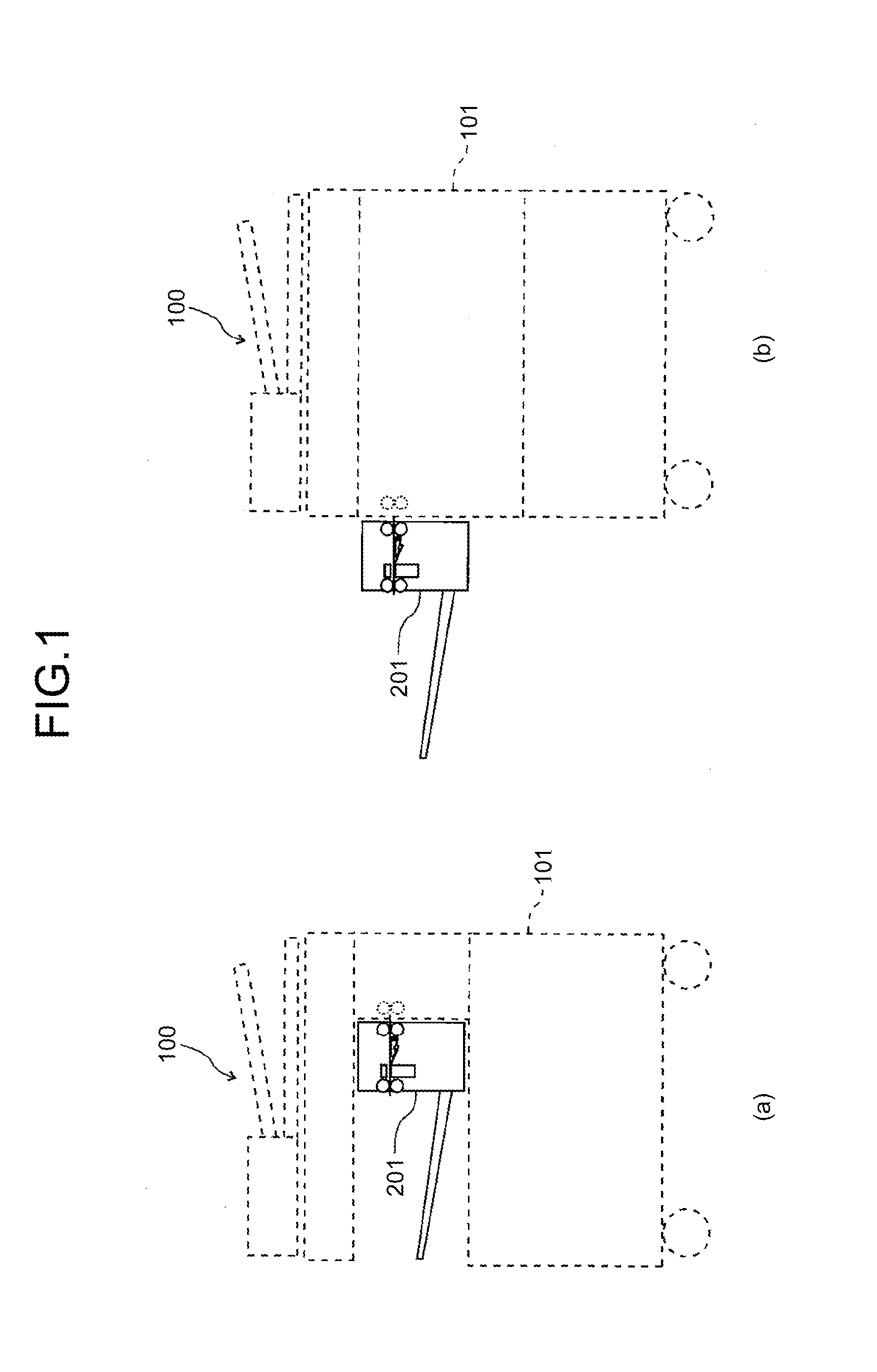
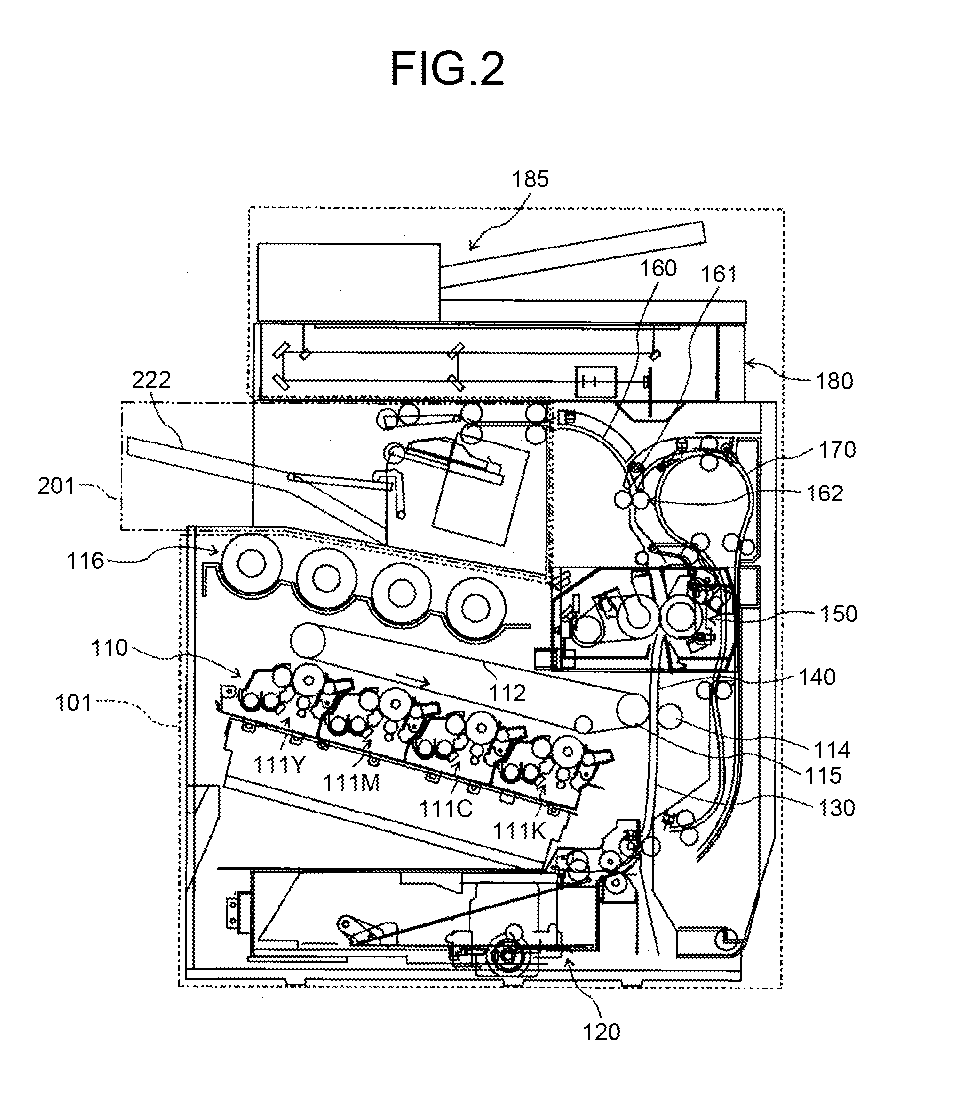
[0040]FIGS. 1(a) and 1(b) are schematic configuration diagrams illustrating examples of an entire configuration of an image forming apparatus according to an embodiment of the present invention. FIG. 1(a) shows an example of an image forming apparatus 100 configured that a sheet post-processing apparatus 201 as a sheet binding device is incorporated in an image forming apparatus main body 101 as an image forming means that forms an image on a sheet on the basis of an input image. FIG. 1(b) shows another example of the image forming apparatus 100 configured that the sheet post-processing apparatus 201 is connected to the image forming apparatus main body 101.

[0041]Incidentally, the image forming apparatus 100 according to the present embodiment is an electrophotographic image forming apparatus that forms an image formed of toner images on a sheet; however, the presen...


PUM

PropertyMeasurementUnit
binding forceaaaaaaaaaa
widthaaaaaaaaaa
electricalaaaaaaaaaa

Abstract

The present invention is concerning a method for attaching a pair of crimping members in a sheet binding device that binds a sheet bundle by engagement of the pair of crimping members, wherein at least one of the crimping members is attached to a member to which the one of the crimping members is to be attached in a state where the pair of crimping members is in engagement.

Description

CROSS-REFERENCE TO RELATED APPLICATIONS[0001]The present application claims priority to and incorporates by reference the entire contents of Japanese Patent Application No. 2013-155015 filed in Japan on Jul. 25, 2013.BACKGROUND OF THE INVENTION[0002]1. Field of the Invention[0003]The present invention relates to a method for attaching crimping members, a sheet binding device, and an image forming apparatus.[0004]2. Description of the Related Art[0005]Conventionally, there are known a sheet binding device for binding a bundle of sheets on which images have been formed and an image forming apparatus equipped with the sheet binding device.[0006]In International Publication Pamphlet No. WO 2009 / 110298, there is described a crimping sheet binding device that binds a bundle of sheets by crimping the sheets without using a metal staple in such a way that the sheet binding device strongly engage crimping teeth, which are a pair of jagged crimping members, thereby entwining fibers of the she...

Claims


Application Information

Patent Timeline
Patent Type & Authority Applications(United States)
IPC IPC(8): B42C13/00
CPCB42C13/00B42C5/02B65H37/04G03G15/60G03G15/6541G03G21/1609G03G2215/00848G03G2221/1696B65H2301/5126B65H2301/51616B42B5/00Y10T29/49826B42C1/12B31F5/02B31F2201/00G03G2215/00852
Inventor TAKAHASHI, WATARUSUZUKI, NOBUYOSHIMATSUSHITA, SHINGOKOSUGE, KATSUHIROSHIBASAKI, YUUSUKEYOSHIDA, RYUJISAITO, TAKASHIMUSHA, AKIHIROMORINAGA, TAKUYAOKAMOTO, IKUHISA
Owner RICOH KK
Why Eureka
Try Eureka