Pump unit of electronic control brake system

a technology of electronic control and brake system, which is applied in the direction of braking system, piston pump, positive displacement liquid engine, etc., can solve the problems of vibration and noise, vibration and noise, vibration and noise, etc., and achieve the effect of preventing vibration and noise and reducing vibration and nois

Inactive Publication Date: 2015-01-29
HL MANDO CORP
View PDF4 Cites 41 Cited by
  • Summary
  • Abstract
  • Description
  • Claims
  • Application Information

AI Technical Summary

Benefits of technology

[0019]As is apparent from the above, the pump unit of the electronic control brake system can offset a repulsive force generated by a piston and reduce vibration and noise by arranging at least one pair of piston pumps in line with each other, and disposing a pressing member configured to pump the piston pump so as to face the piston.
[0020]In addition, the pump unit of the electronic control brake system can ensure a weight balance by preventing a center of gravity of a pressing member configured to pump a piston of a piston pump from being eccentrically positioned from the center of a rotating shaft of a motor, and also prevent vibration and noise caused by an eccentric rotation in the conventional technology.

Problems solved by technology

When the piston of the piston pump driven by a single motor performs a reciprocating motion, for example, when the piston moves from a top dead center to a bottom dead center, a repulsive force is generated in a linear direction in which the piston is moved, causing vibration and noise.
That is, one pair of piston pumps alternately generates a repulsive force through pistons in a direction of the motor shaft, vibration and noise occur.
In addition, a rotary force generated by the motor is provided in the form of an eccentric rotary force by the eccentric bearing or the eccentric shaft, and such a structural feature causes weight imbalance, leading to vibration and noise at the time of eccentric rotation.

Method used


Image

  • Pump unit of electronic control brake system
  • Pump unit of electronic control brake system
  • Pump unit of electronic control brake system

Examples


Embodiment Construction

[0025]Reference will now be made in detail to the preferred embodiments of the present invention, examples of which are illustrated in the accompanying drawings. These embodiments are provided so that this disclosure will be thorough and complete, and will fully convey the spirit and scope of the present invention to those skilled in the art. Other embodiments may also be provided. Constituent elements other than elements constituting essential features of the present invention may be omitted from the drawings, for clarity of description. In the drawings, the widths, lengths, and thicknesses of constituent elements may be exaggerated for clarity and convenience of illustration. Like reference numerals refer to like elements throughout.

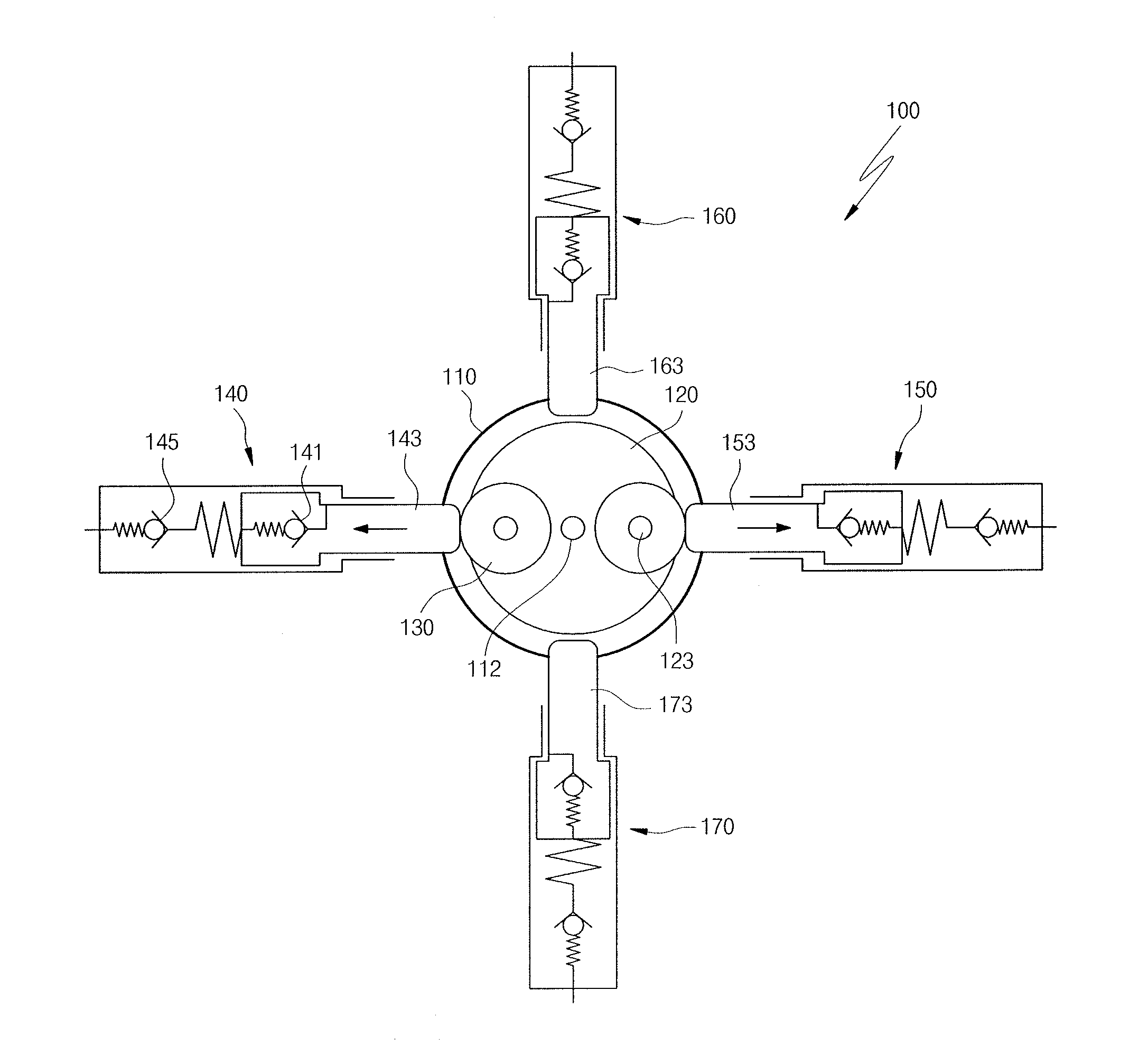
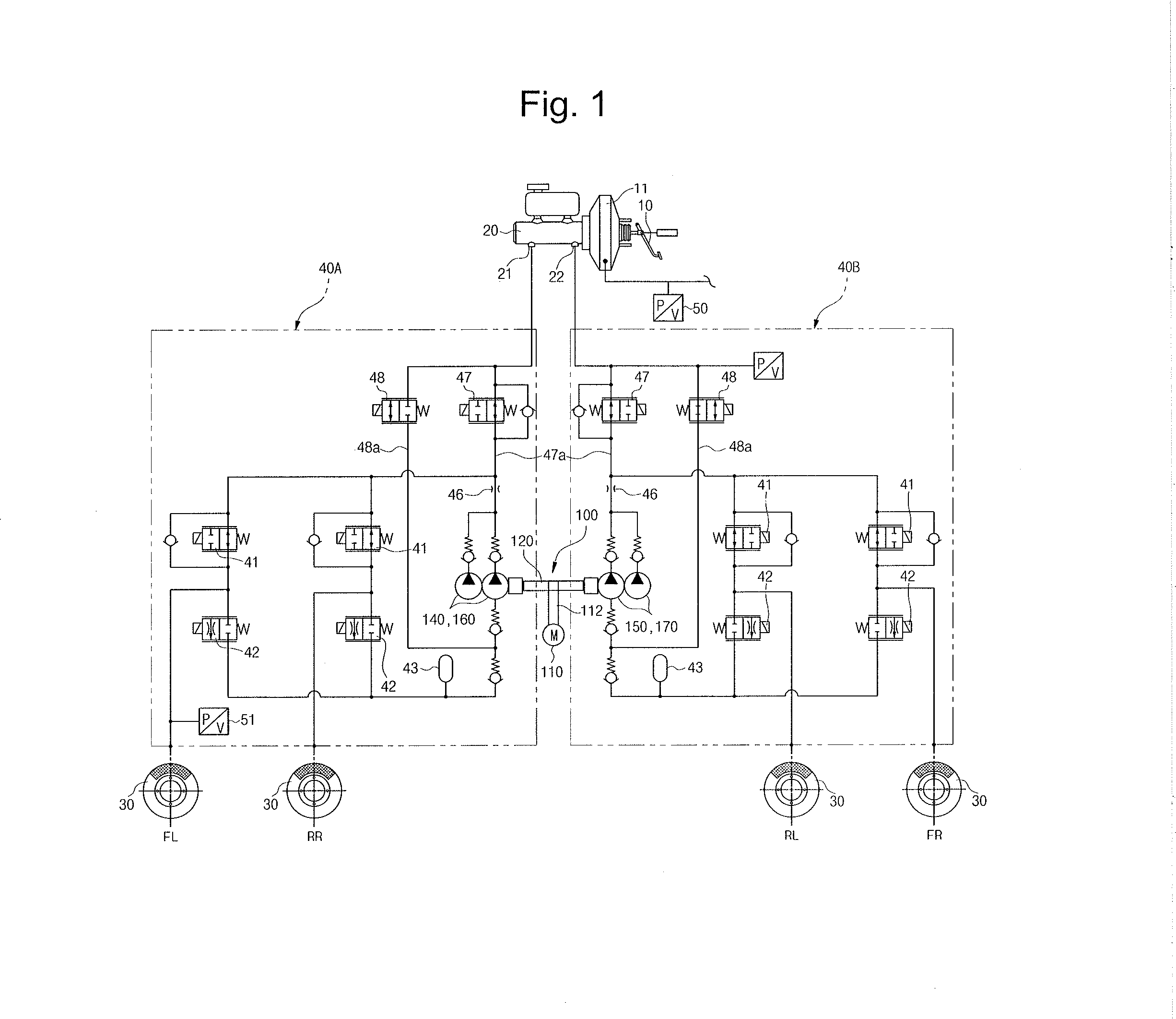
[0026]FIG. 1 is a hydraulic circuit diagram illustrating an electronic control brake system according to an embodiment of the present invention.

[0027]Referring to FIG. 1, an electronic control brake system adopting the present invention includes a brak...


PUM


Abstract

Disclosed is a pump unit of an electronic control brake system installed in a bore formed in a modulator block, the pump unit including a motor having a rotating shaft, a carrier having a center portion thereof installed on the rotating shaft, and provided with connecting shafts that are spaced apart from the center portion to both sides by a predetermined interval to be disposed in line with each other, a pressing member installed on each of the connecting shafts, and a first piston pump and a second piston pump each provided with a piston configured to be reciprocated by making contact with an outer circumferential surface of the pressing member according to rotation of the carrier, the first piston pump and the second piston pump disposed in line with each other.

Description

CROSS-REFERENCE TO RELATED APPLICATIONS[0001]This application claims the benefit of Korean Patent Application No. 2013-0087720, filed on Jul. 25, 2013 in the Korean Intellectual Property Office, the disclosure of which is incorporated herein by reference.BACKGROUND[0002]1. Field[0003]Embodiments of the present invention relate to a pump unit of an electronic control brake system, and more particularly, to a pump unit of an electronic control brake system capable of reducing vibration and noise generated at the time of operation of a piston pump by improving a structure to operate the piston pump.[0004]2. Description of the Related Art[0005]In general, an electronic control brake system is designed to obtain a powerful and stable braking force by effectively preventing slippage of a vehicle, and the electronic control brake system has been developed in several divisions: an anti-lock brake system (ABS) for preventing skidding of wheels at the time of braking, a brake traction control...

Claims


Application Information

Patent Timeline
Patent Type & Authority Applications(United States)
IPC IPC(8): B60T10/04B60T13/14
CPCB60T13/143B60T10/04B60T13/66B60T17/02B60T13/146B60T13/662B60T13/686B60T17/221B60T8/4031B60T8/4872F04B1/0417F04B9/04F04B9/042
Inventor RYU, DONG-YO
Owner HL MANDO CORP
Why Eureka
Try Eureka