
Mining vehicle

a technology for mining vehicles and mining equipment, applied in the direction of process and machine control, distance measurement, instruments, etc., can solve the problem of reducing the speed of the vehicl

Active Publication Date: 2015-01-29
NIHON KENKI CO LTD
View PDF0 Cites 6 Cited by
  • Summary
  • Abstract
  • Description
  • Claims
  • Application Information

AI Technical Summary

Benefits of technology

The invention allows the vehicle to detect the distance in front and adjust its speed accordingly. This is done by measuring the shape of the road and the vehicle's status, which prevents incorrect detection of obstacles. This results in a safer and more stable mining vehicle.

Problems solved by technology

However, if the traveling road is curved, the radar device may erroneously detect an obstacle located outside the traveling road and reduce a speed of the vehicle regardless of the fact that a distance between the vehicle and other vehicles is sufficient.

Method used


Image

  • Mining vehicle
  • Mining vehicle
  • Mining vehicle

Examples


first embodiment

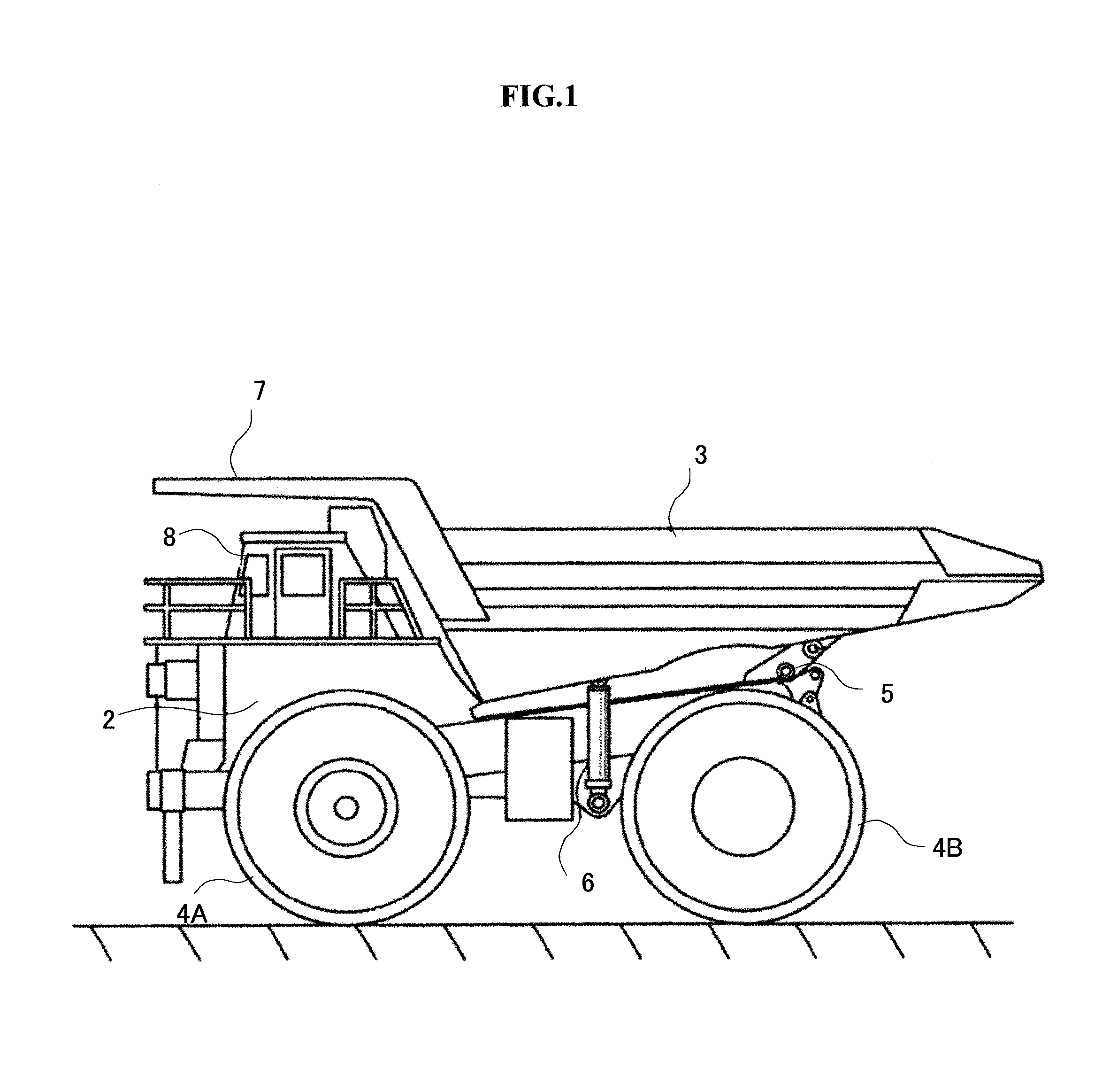
[0025]FIG. 1 is a side view of a mining vehicle according to a first embodiment of the invention. The dump truck (vehicle) 1 illustrated in FIG. 1 mainly includes a vehicle body 2 formed of a robust frame structure, a vessel (bed) arranged on the vehicle body 2 and capable of being tilted, front wheels 4A coupled to the vehicle body 2, and rear wheels 4B coupled to the vehicle body 2.

[0026]The vehicle body 2 has an engine (not illustrated) for driving the rear wheels 4B. The engine includes an engine control unit (hereinafter referred to as an ECU), for example. A rotational speed of the engine is controlled by controlling, on the basis of a command signal from the ECU, a flow rate of a fuel to be supplied. A control device 100 (refer to FIG. 3) to be described later outputs a command signal to the ECU and thereby controls the speed of the vehicle 1.

[0027]The vessel 3 is provided in order to load materials such as broken stones and is coupled to the vehicle body 2 through a pin coup...

second embodiment

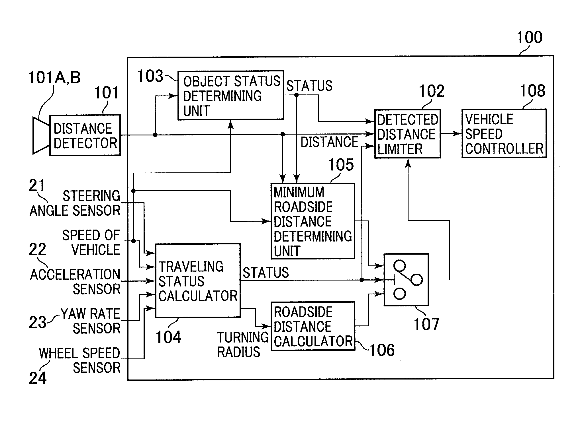
[0051]Hereinafter, the mining vehicle according to a second embodiment of the invention will be described with reference to the accompanying drawings. FIG. 5 is a control block diagram illustrating a configuration of the control device included in the mining vehicle according to the second embodiment of the invention. In FIG. 5, reference numerals that are the same as those illustrated in FIGS. 1 to 4 denote the same parts as those illustrated in FIGS. 1 to 4, and hence, a detailed description thereof is omitted.

[0052]Although the mining vehicle according to the second embodiment of the invention is illustrated in FIG. 5 and structured from devices that are substantially the same as the first embodiment, the following configuration is different from the first embodiment.

[0053]The mining vehicle according to the second embodiment of the invention includes an object status determining unit 103 as well as the configuration of the control device 100 according to the first embodiment. Th...

third embodiment

[0059]Hereinafter, the mining vehicle according to a third embodiment of the invention will be described with reference to the accompanying drawings. FIG. 6 is a control block diagram illustrating a configuration of the control device included in the mining vehicle according to the third embodiment of the invention. FIG. 7 is a flowchart of details of a process to be executed by the control device included in the mining vehicle according to the third embodiment of the invention. In FIGS. 6 and 7, reference numerals that are the same as those illustrated in FIGS. 1 to 5 denote the same parts as those illustrated in FIGS. 1 to 5, and hence, a detailed description thereof is omitted.

[0060]Although the mining vehicle according to the third embodiment of the invention is illustrated in FIG. 6 and configured by devices that are substantially the same as the second embodiment, the following configuration is different from the second embodiment.

[0061]In the configuration of the control devi...


PUM


Abstract

A mining vehicle is provided, which is capable of appropriately recognizing a condition of a traveling road in front of the vehicle, preventing an obstacle on a roadside from being erroneously detected by a distance detector, and controlling the speed of the vehicle in a stable manner even when the vehicle is approaching a curved portion of the road from a linear portion of the road.The mining vehicle that travels on a transport road of a mining site includes: a minimum roadside distance determining unit; a traveling status calculator configured to calculate traveling status of the vehicle and a turning radius of the vehicle; a roadside distance calculator configured to calculate a roadside distance between the vehicle and a roadside of the transport road; a roadside distance selector configured to select and output a minimum roadside distance if the vehicle is in a rectilinearly traveling state and select and output the roadside distance calculated with the roadside distance calculator if the vehicle is in a turning state; a detected distance limiter configured to disable a signal representing the distance, detected with the distance detector, between the vehicle and the object and the relative speed if the distance between the vehicle and the object is larger than a distance represented by a signal selected and output from the roadside distance selector; and a vehicle speed controller configured to control the speed of the vehicle on the basis of a signal output from the detected distance limiter.

Description

TECHNICAL FIELD[0001]The present invention relates to a mining vehicle, and more particularly to a mining vehicle having a vehicle speed control unit configured to detect other vehicles traveling in front of the mining vehicle on a transport road of a mining site and to control a speed of the mining vehicle.BACKGROUND ART[0002]A mineral excavated at a mining site is loaded onto a mining vehicle such as a dump truck at an excavation site, transported by the mining vehicle and collected to a collection site or other places. The mining vehicle repeatedly travels back and forth between the excavation site and the collection site. For the better profit of mining business, it is requested that the transportation efficiency of the mining vehicle be enhanced.[0003]For the sake of the improvement, there is a mining vehicle that has a radar device for measuring a distance to an obstacle located in front of the mining vehicle on a traveling road and to an object detection device for controllin...

Claims


Application Information

Patent Timeline
IPC IPC(8): B60W30/14G05D1/02
CPCG05D1/021B60W30/143G05D1/024G05D1/0257B60W2720/10B60Y2200/142B60W2552/30
Inventor ICHINOSE, MASANORIYASUDA, TOMOHIKOSATO, TAKAYUKITANAKA, WATARU
Owner NIHON KENKI CO LTD
Learn More