
Groundwater remediation apparatus and method

a groundwater remediation and apparatus technology, applied in the direction of fluid removal, sealing/packing, borehole/well accessories, etc., can solve the problems of contaminated vapor entering the surrounding structure, difficult to capture all the air injected into the groundwater, and serious health risks

Inactive Publication Date: 2015-02-05
ABOUODAH MOHAMED
View PDF7 Cites 8 Cited by
  • Summary
  • Abstract
  • Description
  • Claims
  • Application Information

AI Technical Summary

Benefits of technology

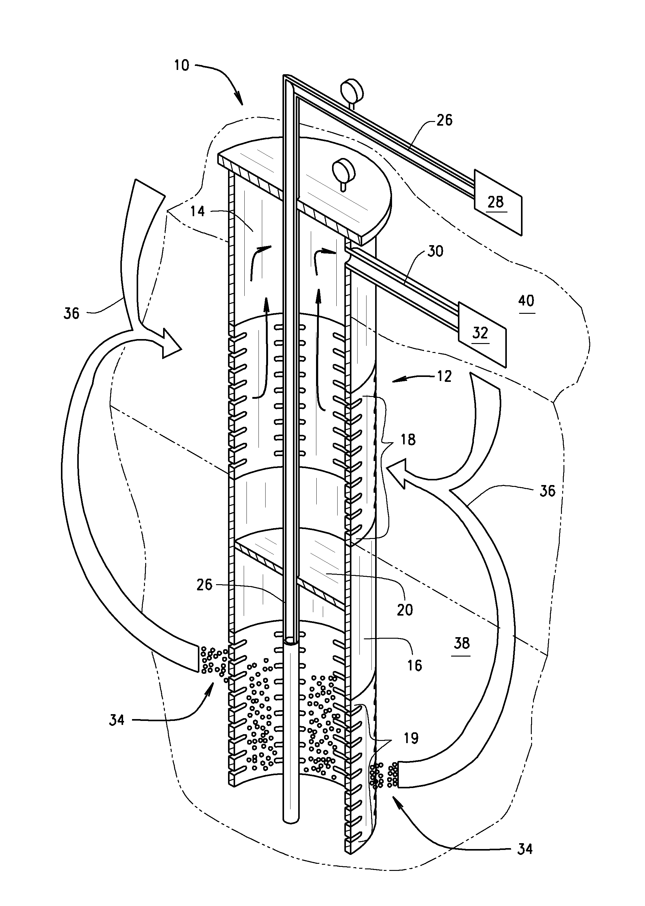
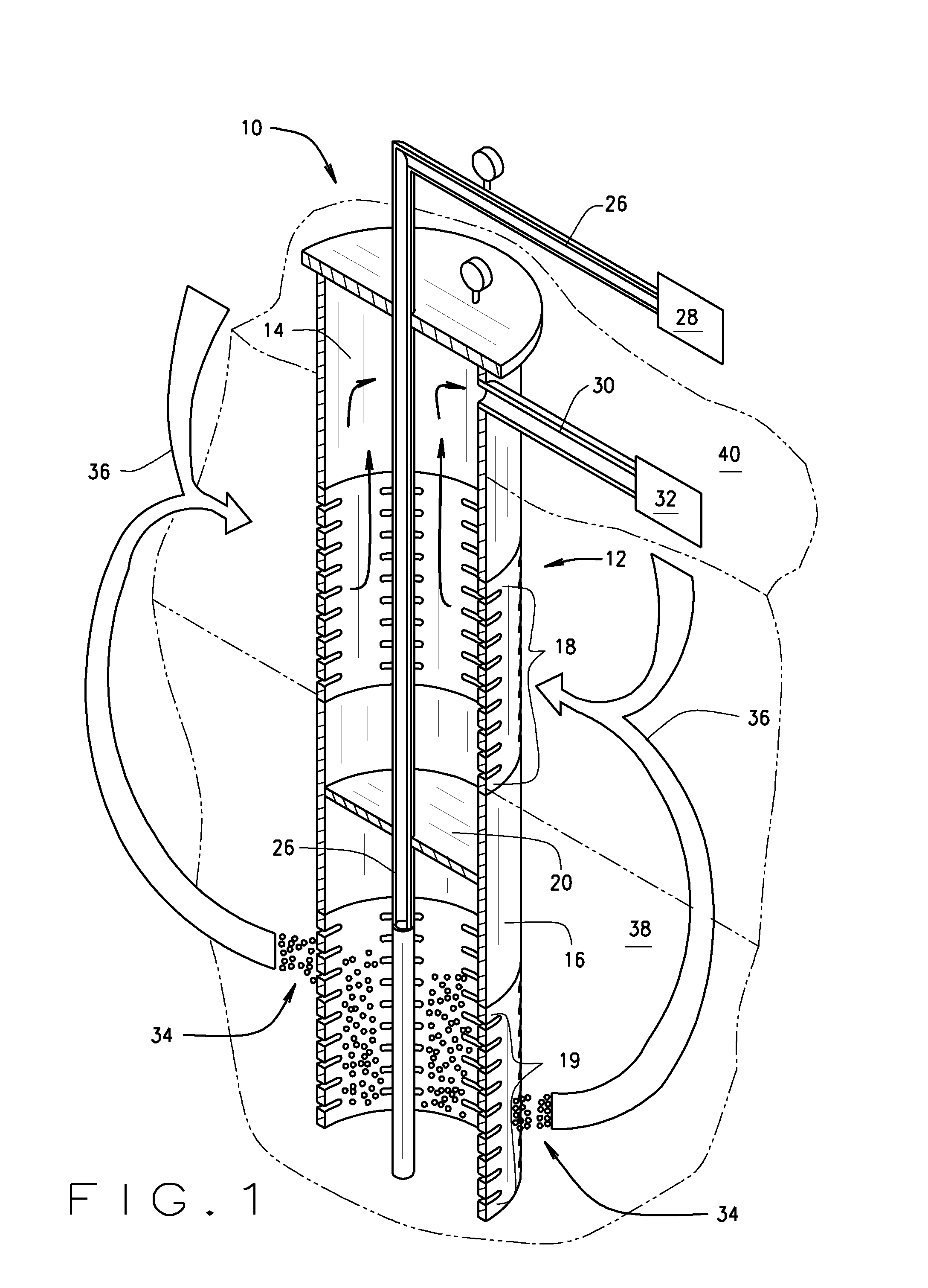
The present invention provides an apparatus and method for combining the air sparging and soil vapor extraction processes for soil and groundwater remediation at a single installation point. This allows for the removal of contaminants from soil and groundwater through a single process. The apparatus includes an elongated well pipe with upper and lower sections separated by a packer element. Compressed air is introduced into the well pipe through the packer element and exits through the openings in the lower section into the surrounding soil. A vacuum is applied through the openings in the upper section to draw vapors into the well pipe. The soil vapor extractor applies a vacuum to remove contaminants from the soil through the openings in the upper section and conveys them to a treatment destination. This invention provides a more efficient and effective method for remediation of contaminated soil and groundwater.

Problems solved by technology

The spacing apart of the injection and extraction wells presents difficulties in capturing all of the air injected into the groundwater.
In particular, there is often a migration of contaminants to clean areas in the soil, and an intrusion of contaminated vapors into surrounding structures.
The uncollected contaminated air can result in serious health risks and possibly causing explosive conditions depending on the contamination.
Furthermore, the associated trenching between the sparging and extraction points, and the extensive drilling, construction and maintenance that goes along with these tasks, creates additional costs.

Method used


Image

  • Groundwater remediation apparatus and method
  • Groundwater remediation apparatus and method
  • Groundwater remediation apparatus and method

Examples


Embodiment Construction

.

BRIEF DESCRIPTION OF THE DRAWING FIGURES

[0011]The present invention is described herein with reference to the following drawing figures, with greater emphasis being placed on clarity rather than scale:

[0012]FIG. 1 is a schematic view of the apparatus according to the present invention.

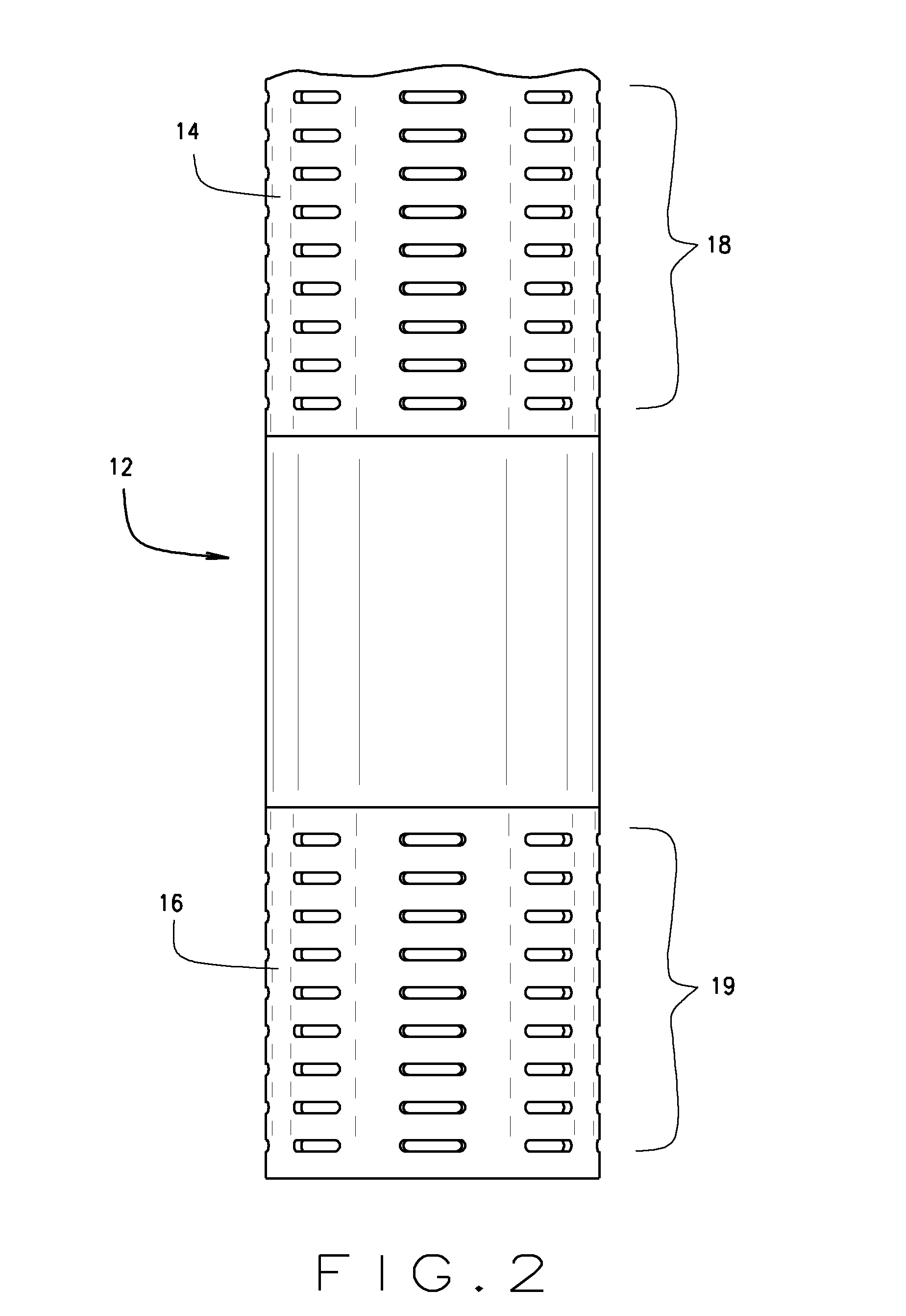
[0013]FIG. 2 is a view in side elevation of a portion of the well pipe according to the present invention.

[0014]FIG. 3 is a cross-sectional view in side elevation of the well pipe according to the present invention.

[0015]FIG. 4 is a cross-sectional view taken along line 4-4 in FIG. 3.

[0016]FIG. 5 is a cross-sectional view in side elevation of the well pipe showing the packer member.

DETAILED DESCRIPTION OF THE INVENTION

[0017]With reference to the drawing figures, an apparatus for combining air sparging and soil vapor extraction processes for groundwater and soil remediation of the present invention is herein described, shown, and otherwise disclosed in accordance with various embodiments of the present...


PUM


Abstract

A well pipe provides for air sparging and soil vapor extraction for groundwater remediation at a single point of entry. An elongated well pipe is provided with a plurality of openings at an upper section and a lower section of the pipe and a packer member for separating the two sections. A conduit for delivering compressed air passes through the packer member into the lower section of the well tube for providing air sparging below the water table level in the ground and a vacuum source is connected to an upper end of the well pipe for drawing vapors from the vadose region in the ground into the pipe through the openings in the upper section of the well tube for transport on to a remediation destination. The conduit is adapted for delivery of remedial enhancing amendments into the surrounding ground through the lower section of the well pipe to further treat the contamination below the ground surface.

Description

FIELD OF THE INVENTION[0001]The invention relates to soil and groundwater remediation and the removal of contaminant vapors from below the ground surface for treatment above ground. In particular, the invention relates to subsurface air sparging and soil vapor extraction.BACKGROUND OF THE INVENTION[0002]Methods are presently being used for removing contaminant vapors from below the ground for treatment above ground. Soil vapor extraction and air sparging processes are commonly performed in two separate below grade structures and may generally be used in combination in performing such methods. Soil vapor extraction methods extract vapors from the soil vadose zone above the water table by applying a vacuum to pull the vapors out of the ground. Air sparging methods pump air underground to help extract vapors from groundwater and wet soil found beneath the water table. The pressurized air introduced through sparging promotes the chemicals to evaporate faster, and facilitates the soil va...

Claims


Application Information

Patent Timeline
IPC IPC(8): B09C1/00
CPCB09C1/005B09C1/002B09C2101/00
Inventor ABOUODAH, MOHAMED
Owner ABOUODAH MOHAMED
Learn More