

Polarizable connection structure and device including the same
a polarizable connection and structure technology, applied in the field of polarizable connection, can solve the problems of limited functions which can be fulfilled by the single polarizable structure as a single body
- Summary
- Abstract
- Description
- Claims
- Application Information
AI Technical Summary
Benefits of technology
Problems solved by technology
Method used
Image

Examples
example 1
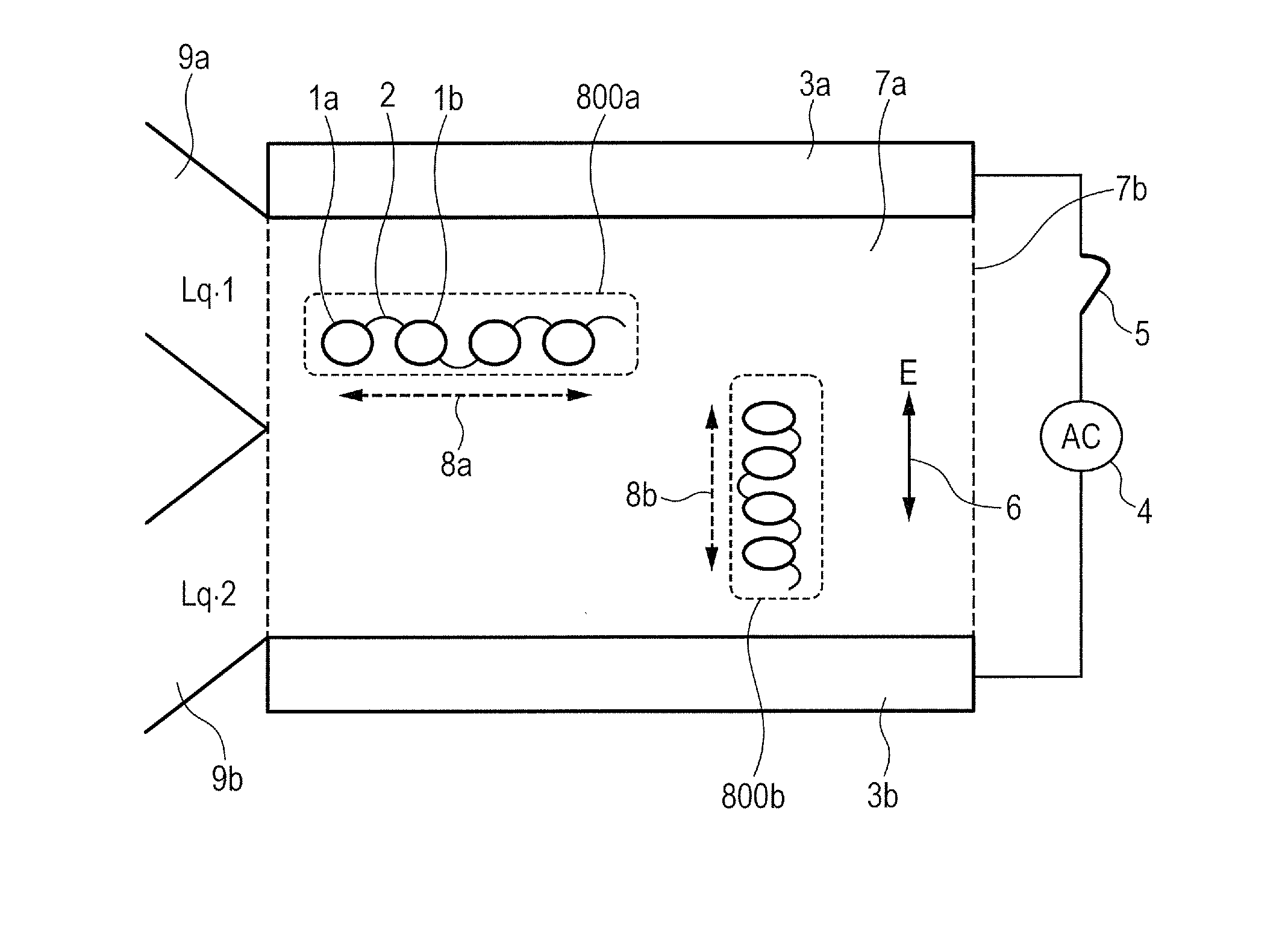
[0051]FIG. 1 is a diagram illustrating a device according to Example 1 of the present invention. The device of the present example includes a liquid chamber 7b filled with an electrolyte 7a, a pair of parallel electrodes 3a and 3b as electric-field application units, and an alternate-current (AC) power supply 4. In the electrolyte 7a, polarizable connection structures 800a and 800b move freely. Each of the polarizable connection structures 800a and 800b includes a plurality of polarizable structures 1a and 1b, each having a polarizable conductive part, and mobile or deformable connector bodies 2 which connect the polarizable structures 1a and 1b to each other. The device of the present example may include a power-supply application switch 5, and flow paths 9a and 9b for supplying or discharging a liquid to / from the liquid chamber 7b. When two kinds of liquid are to be mixed by the device of the present example, different kinds of liquid can be supplied from the two flow paths 9a and...
example 2
[0059]FIG. 4 illustrates a device according to Example 2 of the present invention. The device according to Example 2 has the same configuration as that of Example 1 with the exception that a functional base 21a is connected to polarizable structures 22a similar to those of Example 1 by connector bodies 22b. By adding the functional base 21a to the polarizable connection structure as described in Example 1, the functional base 21a also moves in the liquid chamber in a complex manner to be diffused widely. Therefore, the functions of the functional base 21a can be effectively fulfilled over a wide range in the liquid chamber 7b.
[0060]In the present example, the polarizable connection structure in which the spherical functional base 21a with a radius of 5 μm, which has a surface having a hydrophobic part, is used. As the polarizable structure 22a, a spherical polarizable structure having a radius of 3 μm is used. For one polarizable connection structure, three polarizable structures 2...
example 3
[0062]FIG. 5 illustrates a device according to Example 3 of the present invention. The device of Example 3has the same configuration as that of Example 2 with the exception that a functional base 28 is provided with a function of recognizing specifically a target substance 27a. The functional base 28 is a cuboid having dimensions: (height 10 μm)×(width 10 μm)×(depth 5 μm). By forming a recess having dimensions: (height 6 μm)×(width 5 μpm)×(depth 5 μm) on an upper surface of the functional base 28, the functional base 28 has a concave shape. When the four polarizable connection structures including the functional base 28 connected to the polarizable structure are moved freely in the liquid chamber 7b, the structures 27a, each having a shape fittable to an unevenness structure of the functional base 28, can be specifically captured over a wide range in the liquid chamber 7b. Therefore, the target substance 27a which binds specifically to the functional base 28 and a substance 27b whic...
PUM
| Property | Measurement | Unit |
|---|---|---|
| radius | aaaaa | aaaaa |
| radius | aaaaa | aaaaa |
| distance | aaaaa | aaaaa |
Abstract
Description
Claims
Application Information