Multifunctional motor controller

A motor controller and multi-functional technology, applied in the direction of DC motor rotation control, DC motor speed/torque control, control system, etc., can solve the problems of single motor control function, single, multiple interfaces, etc., and achieve the effect of protecting the motor

Inactive Publication Date: 2021-07-23
YELLOW RIVER CONSERVANCY TECHN INST
View PDF4 Cites 0 Cited by
  • Summary
  • Abstract
  • Description
  • Claims
  • Application Information

AI Technical Summary

Problems solved by technology

[0002] With the development of industrialization, the technical level of my country's industrial enterprises is constantly improving. In many automation equipment, the use of motors is required to ensure the normal operation of industrial enterprises, improve the production efficiency of industrial enterprises, and ensure the quality of industrial processing. Motors are used as daily There are many devices used in life, which greatly facilitate people's life style, but at present, the control function of the motor on the market is too single, and it can only rotate at a single constant speed, and in the controller module, each The modules are scattered and independent from each other, resulting in too many interfaces and increased safety hazards. Without real-time monitoring, it is impossible to know the operating status of the motor in a certain period of time.

Method used


Image

  • Multifunctional motor controller
  • Multifunctional motor controller
  • Multifunctional motor controller

Examples


Embodiment 1

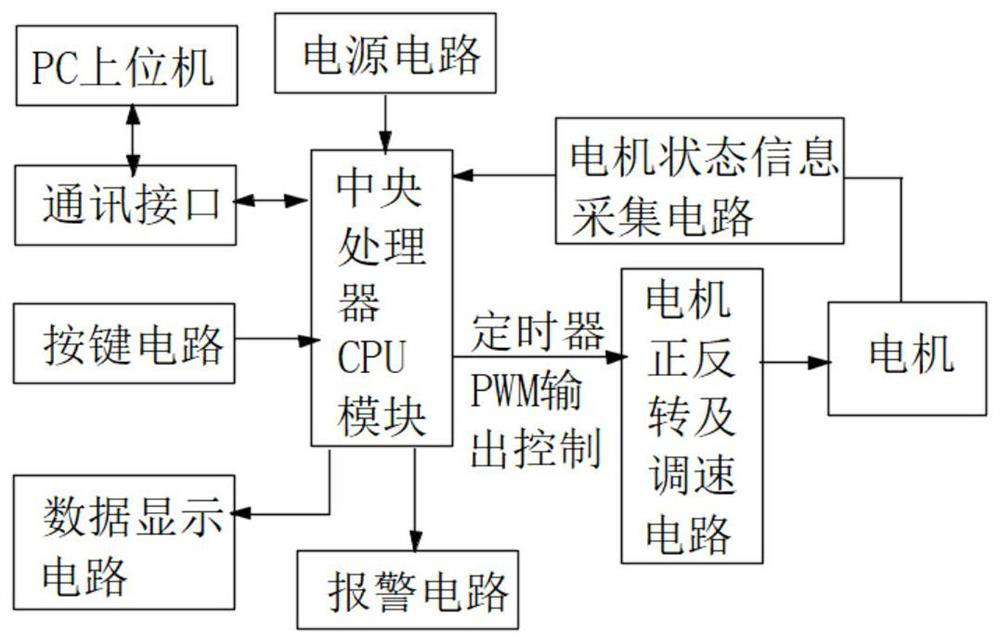
[0018] Example 1: See figure 1 , a multifunctional motor controller, including PC host computer, communication interface, button circuit, power supply circuit, central processing unit CPU module, data display circuit, alarm circuit, motor forward and reverse and speed regulation circuit, motor, motor status information Acquisition circuit, the PC upper computer sends commands and receives information to the CPU through the communication interface, the button circuit is used for function selection, the central processing unit CPU module is used to control the operation of the entire circuit, and the data display circuit is used for displaying the motor speed. The alarm circuit is used for alarm, the forward and reverse motor and speed regulation circuit are used to control the operation of different functions of the motor, and the motor status information acquisition circuit is used to protect the motor.

Embodiment 2

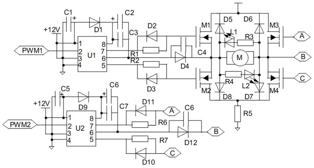
[0019] Embodiment 2: On the basis of Embodiment 1, please refer to figure 2 , the forward and reverse rotation of the motor and the speed regulation circuit are controlled by two drivers U1-U2, the pin 1 of the driver U1 is connected to the anode of the capacitor C1, the anode of the diode D1, +12V voltage, the pin 3 of the driver U1, the lead of the driver U1 Pin 4, the negative pole and ground terminal of capacitor C1, pin 2 of driver U1 is connected to the PWM1 output terminal of the central processing unit CPU, pin 5 of driver U1 is connected to resistor R2 and the cathode of diode D3, pin 6 of driver U1 is connected to the capacitor C3, the negative pole of capacitor C2, capacitor C4 and the anode of diode D4, pin 7 of driver U1 is connected to resistor R1 and the cathode of diode D2, pin 8 of driver U1 is connected to the other end of capacitor C3, the cathode of diode D1 and capacitor C2 The anode of the diode D2 is connected to the other end of the resistor R1 and the...

Embodiment

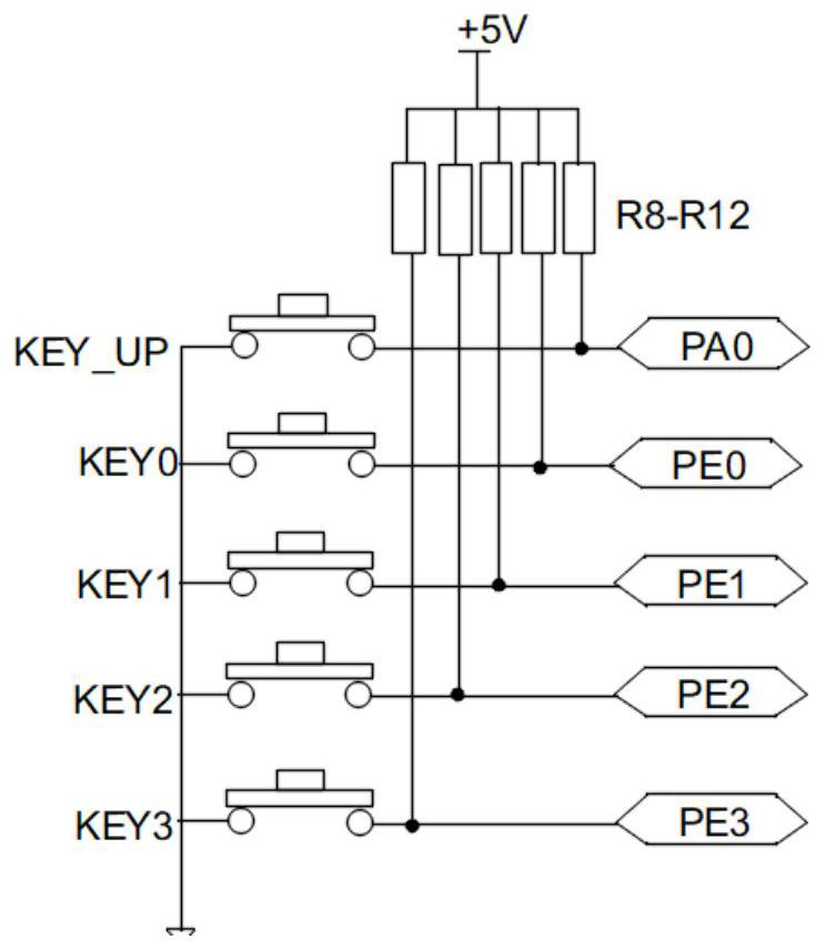
[0020] Embodiment 3: On the basis of Embodiment 2, please refer to Figure 3. The key circuit is controlled by the key KEY_UP and the key KEY0-KEY3. The key KEY_UP is connected to the key KEY0-KEY3 and the ground terminal. The PA0 end of the processor CPU, the other end of the button KEY0 is connected to the resistor R11 and the PE0 end of the central processing unit CPU, the other end of the button KEY1 is connected to the resistor R10 and the PE1 end of the central processing unit CPU, the other end of the button KEY2 is connected to the resistor R9 and The PE2 end of the central processing unit CPU, the other end of the key KEY3 is connected to the resistor R8 and the PE3 end of the central processing unit CPU, and the other end of the resistors R8-R12 is connected to the +5V capacitor.

[0021]The working principle of the present invention is: the circuit is powered on, and the STM32 microcontroller outputs PWM signals to realize different functions of the motor through the ...


PUM


Abstract

The invention discloses a multifunctional motor controller, which comprises a PC (Personal Computer) upper computer, a communication interface, a key circuit, a power supply circuit, a central processing unit (CPU) module, a data display circuit, an alarm circuit, a motor positive and negative rotation and speed regulation circuit, a motor and a motor state information acquisition circuit. The PC upper computer carries out instruction sending and information receiving on the CPU through the communication interface. The key circuit is used for function selection, the CPU module is used for controlling the operation of the whole circuit, the data display circuit is used for displaying the rotating speed of the motor, the alarm circuit is used for alarming, the motor positive and negative rotation and speed regulation circuit is used for controlling the operation of different functions of the motor, and the motor state information acquisition circuit is used for protecting the motor. According to the multifunctional motor controller, positive and negative rotation control is conducted on the motor through the microcontroller, the rotating speed of the motor can be adjusted, the multifunctional control over the motor is achieved, the high-precision control over the motor is achieved through the motor driver, and the motor is protected through the real-time information collection of the motor.

Description

technical field [0001] The invention relates to the field of motor controllers, in particular to a multifunctional motor controller. Background technique [0002] With the development of industrialization, the technical level of my country's industrial enterprises is constantly improving. In many automation equipment, the use of motors is required to ensure the normal operation of industrial enterprises, improve the production efficiency of industrial enterprises, and ensure the quality of industrial processing. Motors are used as daily There are many devices used in life, which greatly facilitate people's life style, but at present, the control function of the motor on the market is too single, and it can only rotate at a single constant speed, and in the controller module, each The modules are scattered and independent from each other, resulting in too many interfaces and increased safety hazards. Without real-time monitoring, it is impossible to know the operating status of...

Claims


Application Information

Patent Timeline
Patent Type & Authority Applications(China)
IPC IPC(8): H02P7/00H02P7/03
CPCH02P7/00H02P7/03
Inventor 高杨朱海英李杰张慧宁赵转莉郭红山杨筝刘云潺
Owner YELLOW RIVER CONSERVANCY TECHN INST
Why Eureka
Try Eureka