Illumination apparatus and lighting device used thereby

a technology of illumination apparatus and lighting device, which is applied in the direction of lighting apparatus, electrical apparatus, light sources, etc., can solve the problems of disadvantageous consumption of electric power, and achieve the effect of reducing power consumption and power consumption

Inactive Publication Date: 2015-02-05
PANASONIC INTELLECTUAL PROPERTY MANAGEMENT CO LTD
View PDF9 Cites 32 Cited by
  • Summary
  • Abstract
  • Description
  • Claims
  • Application Information

AI Technical Summary

Benefits of technology

[0019]In the illumination apparatus relating to the one aspect of the present invention, the control circuit performs on-off switching of each of the light sources in a manner such that an on-period of the light source switch is not overlapped with an on-period of any other of the light source switches. According to the above configuration, the light sources emit light in order, one at a time, and thus current does not simultaneously flow in each of the light sources. As a consequence of the above, it is not necessary to connect a resistant element in series to each of the light sources in order to individually compensate for voltage drop across the light source. Therefore, the illumination apparatus having the above configuration enables reduced power consumption relative to the conventional illumination apparatus described further above. Furthermore, in the illumination apparatus having the above configuration, chromaticity of mixed light emitted collectively from the light sources can be adjusted to a desired chromaticity by adjusting the products of target on-period length and target current magnitude for the light sources, thereby adjusting a ratio of the light sources relative to one another, in terms of a product, for each of the light sources, of luminance and light-emission time.
[0020]Consequently, the above configuration enables reduction in power consumption for an illumination apparatus including a plurality of light sources differing in terms of light-emission color and also in terms of voltage drop thereacross during light-emission.

Problems solved by technology

As a consequence, during lighting of the light sources in the conventional illumination apparatus, electric power is disadvantageously consumed in the resistant elements, which are each connected in series to the corresponding light source in order to individually compensate for the voltage drop across the light source.

Method used


Image

  • Illumination apparatus and lighting device used thereby
  • Illumination apparatus and lighting device used thereby
  • Illumination apparatus and lighting device used thereby

Examples


first embodiment

[0041]The following explains, with reference to FIGS. 1-4, an illumination apparatus relating to a first embodiment of the present invention. Note that the first embodiment is explained for an example in which LEDs are used as light sources.

[0042]1. Circuit Configuration

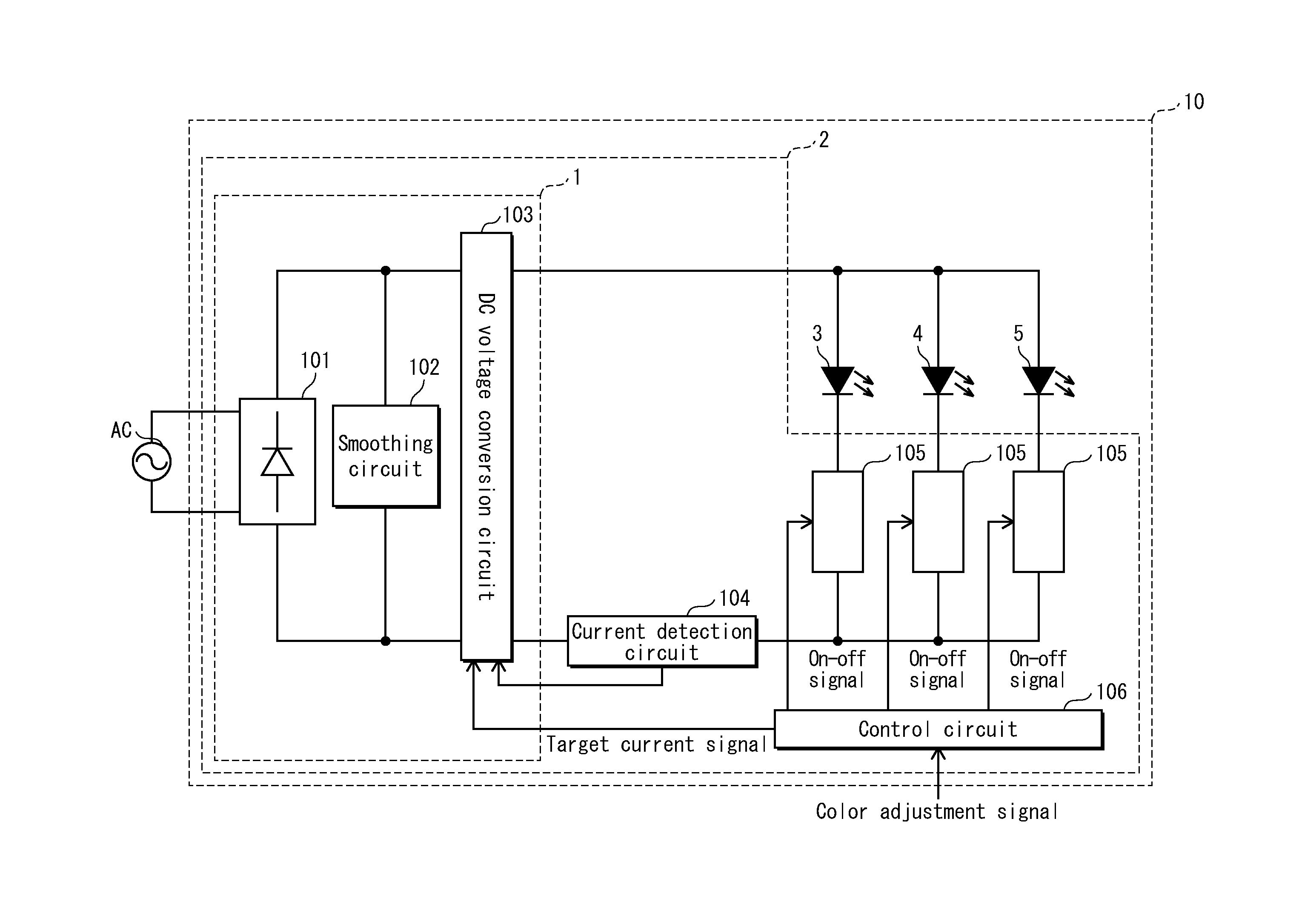
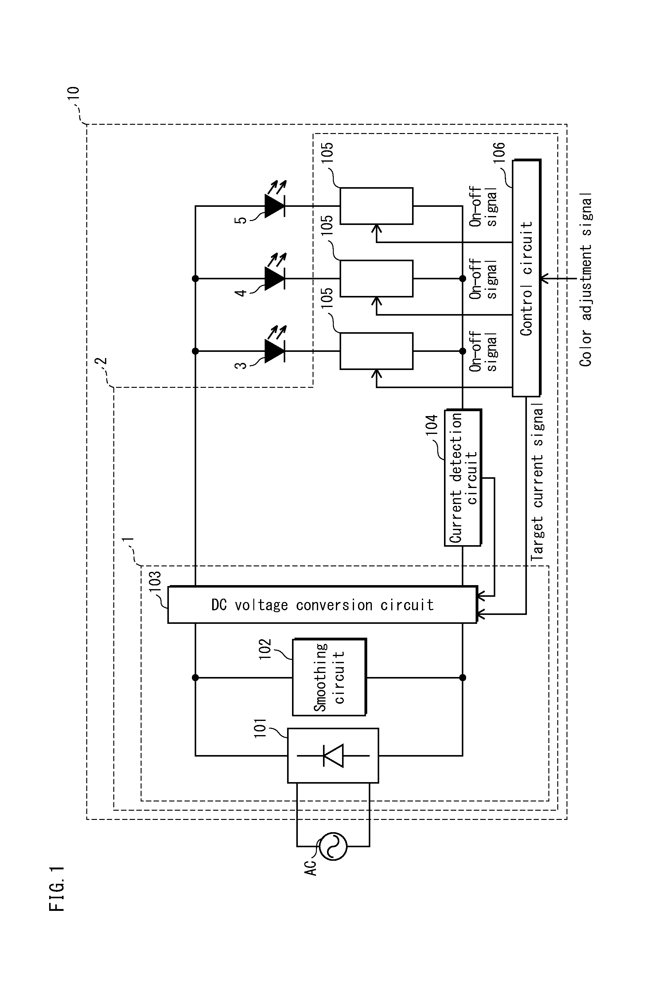
[0043]As illustrated by the block diagram in FIG. 1, an illumination apparatus 10 includes a lighting device 2 and LEDs 3, 4, and 5. The LEDs 3, 4, and 5 differ from one another in terms of light-emission color. In the present embodiment, light-emission colors of the LEDs 3, 4, and 5 are for example red (R), green (G), and blue (B) respectively. The lighting device 2 lights the LEDs 3, 4, and 5 in order, one at a time, at a high speed such that a person is unable to perceive flashing on and off of the LEDs 3, 4, and 5. The above configuration makes it possible to obtain mixed light by mixing light-emission colors of the LEDs 3, 4, and 5. When lighting the LEDs 3, 4, and 5 one by one, the lighting device 2 adjusts a r...

second embodiment

[0073]The following explains a second embodiment of the present invention with reference to the circuit diagram in FIG. 5 and the waveform diagram in FIG. 6. The second embodiment differs from the first embodiment in terms that when target chromaticity indicated by a color adjustment signal varies, a ratio of switches in terms of on-period length is changed for every color adjustment signal data, while output current from a DC voltage conversion circuit remains fixed at a constant value. The following explanation focuses on differences between the first embodiment and the second embodiment. Elements of configuration which are the same as in the first embodiment are labeled using the same reference signs and explanation thereof is omitted.

[0074]As illustrated by the circuit diagram in FIG. 5, an illumination apparatus 210 includes a lighting device 202. The lighting device 202 includes a control circuit 206. The control circuit 206 includes a micro-computer IC2 and a chromaticity tab...

third embodiment

[0077]Color of mixed light is adjusted in the first embodiment through adjustment of a ratio of magnitudes of output current from the DC voltage conversion circuit, and is adjusted in the second embodiment through adjustment of a ratio of on-period lengths of the switching elements. In contrast to the first and second embodiments, in a third embodiment of the present invention, color of mixed light is adjusted through adjustment of both a ratio of magnitudes of output current from a DC voltage conversion circuit and a ratio of on-period lengths of switching elements.

[0078]The following explains the third embodiment with reference to the circuit diagram in FIG. 7 and the waveform diagram in FIG. 8. The third embodiment differs from the first embodiment in terms that a ratio of magnitudes of output current from a DC voltage conversion circuit is adjusted while also adjusting a ratio of on-period lengths of switches. The following explanation focuses on differences between the first em...


PUM


Abstract

An illumination apparatus includes light sources differing from one another in terms of light-emission color and voltage drop when identical current flows therein, switches in one-to-one correspondence with the light sources, a DC power supply circuit, and a control circuit. The control circuit performs a first control of the switches through a time division control method such that an on-period of each switch is not overlapped with that of any other switch. The control circuit also performs a second control to individually control at least one of a target current magnitude, flowing through each switch in the switched-on state, and a target on-period length of each switch, and to adjust a ratio of the plurality of light sources in terms of a product of the target current magnitude and the target on-period length.

Description

CROSS-REFERENCE TO RELATED APPLICATION[0001]The disclosure of Japanese Patent Application No. 2013-161484 filed Aug. 2, 2013 including specification, drawings and claims is incorporated herein by reference in its entirety.TECHNICAL FIELD[0002]The present disclosure relates to an illumination apparatus, and to a lighting device included therein, that causes lighting of a plurality of light sources, differing from one another in terms of light-emission color, and thereby causes the light sources to collectively emit mixed light.BACKGROUND ART[0003]Typically an illumination apparatus includes a plurality of light sources, differing from one another in terms of light-emission color, in order that the illumination apparatus emits light of a desired light-emission color which is a mixture of light emitted from each of the light sources.[0004]FIG. 18 is a circuit diagram of an illumination apparatus disclosed in Japanese Unexamined Patent Application Publication No. 2009-302008. In FIG. 18...

Claims


Application Information

Patent Timeline
Patent Type & Authority Applications(United States)
IPC IPC(8): H05B33/08H05B44/00
CPCH05B33/086H05B45/46H05B45/20H05B45/38H05B45/375H05B45/385
Inventor HASEGAWA, JUNICHIKIDO, HIROSHIHIRAMATSU, AKINORIIDO, SHIGERU
Owner PANASONIC INTELLECTUAL PROPERTY MANAGEMENT CO LTD
Why Eureka
Try Eureka