Magnetic sensor including a lorentz force transducer driven at a frequency different from the resonance frequency, and method for driving a lorentz force transducer

Active Publication Date: 2015-02-05
STMICROELECTRONICS INT NV
View PDF4 Cites 12 Cited by
  • Summary
  • Abstract
  • Description
  • Claims
  • Application Information

AI Technical Summary

Problems solved by technology

However, Lorentz force magnetometers feature non-negligible levels of consumption, as well as not particularly wide bandwidths.
This driving technique is simple to implement; however, it entails that the magnetometer 1, when driven in this way, has a somewhat reduced sensitivity; moreover, the magnetomet

Method used


Image

  • Magnetic sensor including a lorentz force transducer driven at a frequency different from the resonance frequency, and method for driving a lorentz force transducer
  • Magnetic sensor including a lorentz force transducer driven at a frequency different from the resonance frequency, and method for driving a lorentz force transducer
  • Magnetic sensor including a lorentz force transducer driven at a frequency different from the resonance frequency, and method for driving a lorentz force transducer

Examples


Embodiment Construction

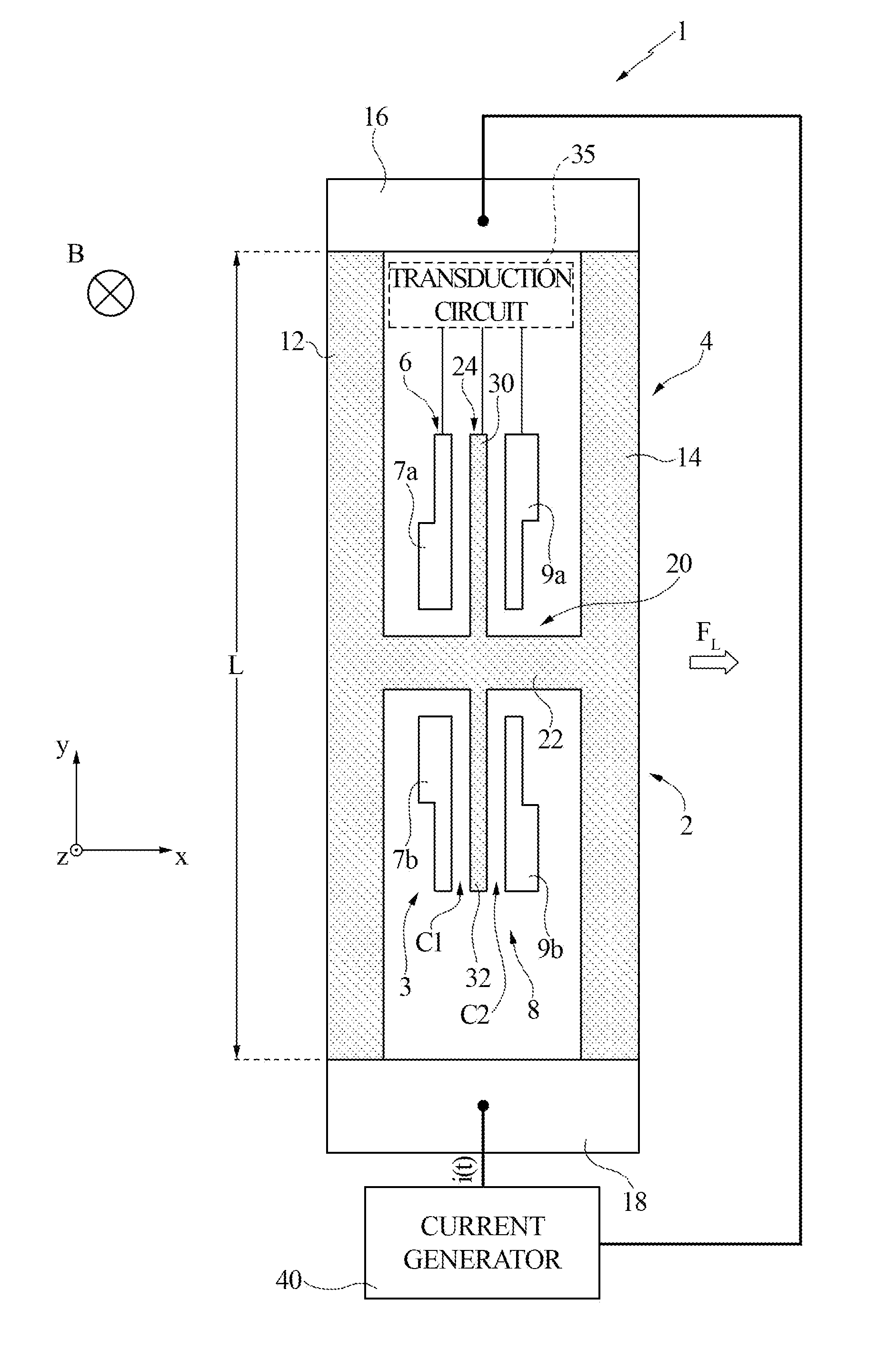
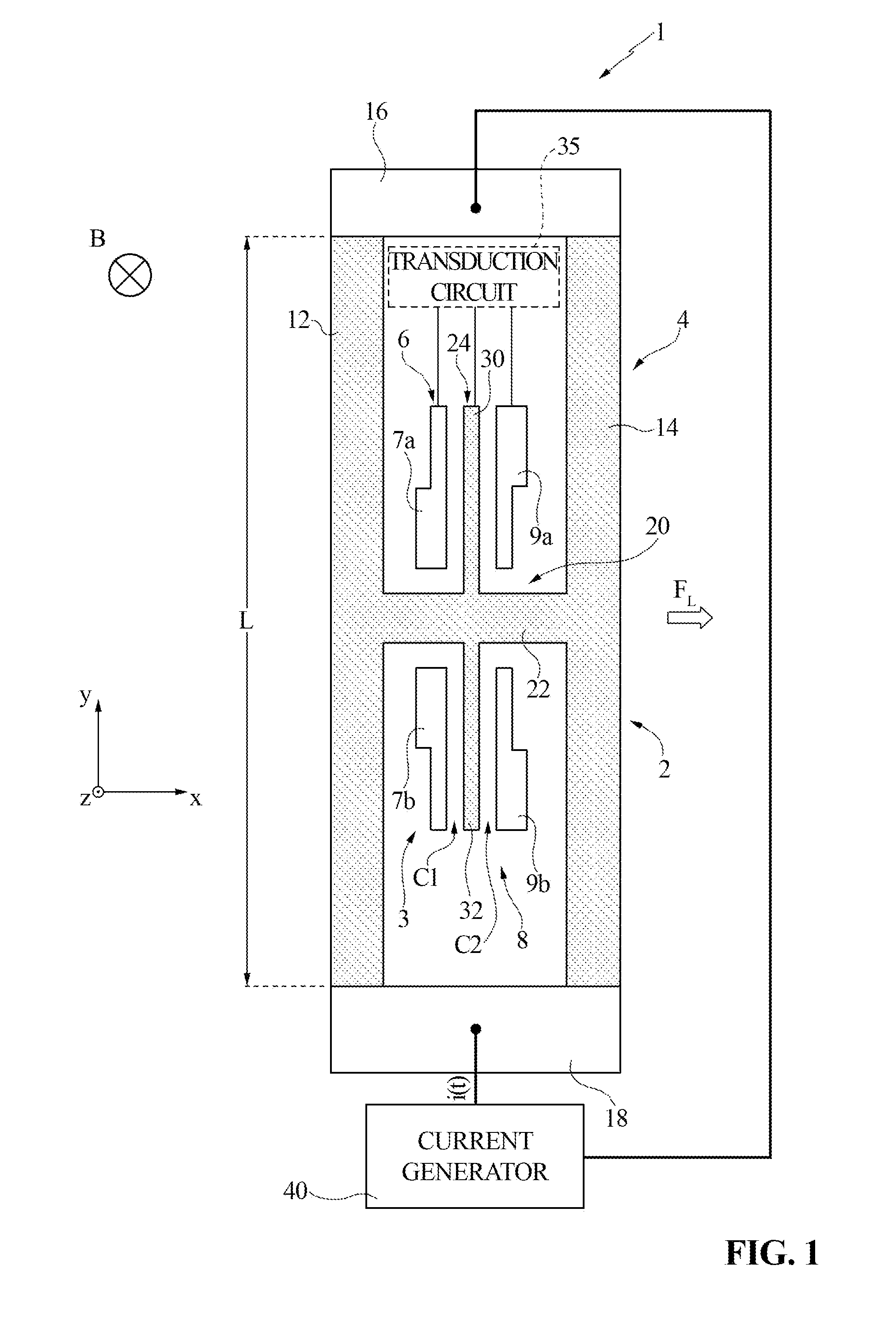
[0045]FIG. 3 illustrates a magnetic sensor 50, which comprises a Lorentz force transducer 55, referred to hereinafter as “transducer 55”, and a current generator 60. Purely by way of non-limiting example, it is assumed that the transducer 55 is the same as the transducer 2 illustrated in FIG. 1; moreover, components of the transducer 55 already present in the transducer 2 illustrated in FIG. 1 are designated by the same reference numbers, except where otherwise specified.

[0046]In detail, the current generator 60 generates a periodic current i(t) with a frequency fi. The waveform of the current i(t) may be, for example, a square or sinusoidal wave.

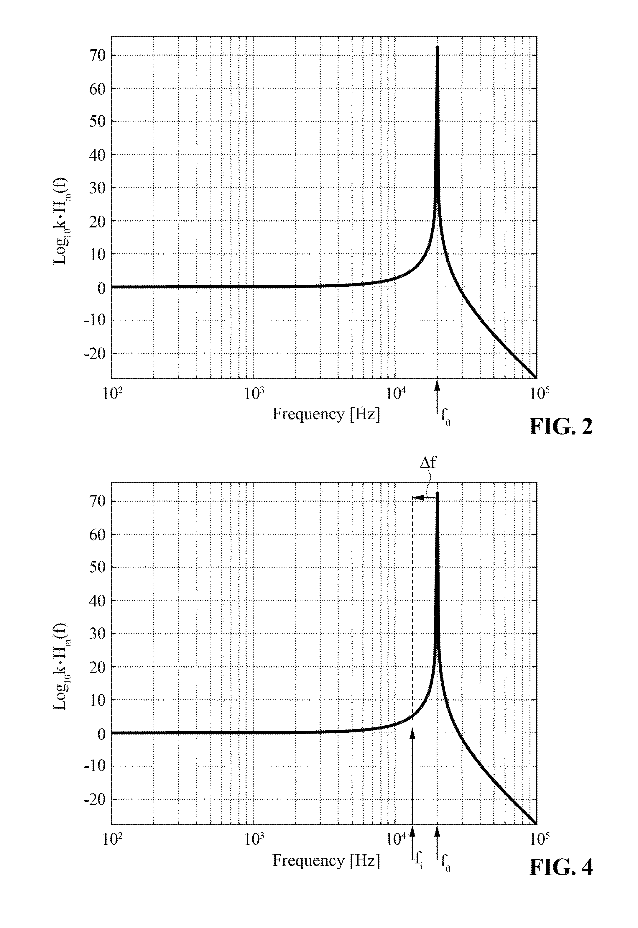
[0047]In greater detail, the transducer 55 has a resonance frequency f0. Furthermore, as illustrated in FIG. 4, the frequency f of the current i(t) is fixed in time and differs from the resonance frequency f0 by a deviation Δf, the modulus of which may be comprised, for example, in the interval [500 Hz-1000 Hz], and in any case is not less ...


PUM


Abstract

A magnetic-field sensor, including: a die, a current generator in the die. The current generator generating a driving current. A Lorentz force transducer also in the die and being configured to obtain measurements of magnetic field based upon the Lorentz force is coupled to the current generator. The transducer having a resonance frequency. The current generator is such that the driving current has a non-zero frequency different from the resonance frequency.

Description

BACKGROUND[0001]1. Technical Field[0002]The present disclosure relates to a magnetic sensor including a Lorentz force transducer, which is driven at a frequency different from its natural resonance frequency. Furthermore, the present disclosure relates to a method for driving a Lorentz force transducer.[0003]2. Description of the Related Art[0004]As is known, today available are the so-called magnetic sensors based upon the Lorentz force, which are also known as Lorentz force magnetometers and exploit, precisely, the Lorentz force to obtain measurements of magnetic field, as described, for example, in U.S. Pat. No. 7,642,692.[0005]Lorentz force magnetometers represent a valid alternative, for example, to Hall sensors and to the so-called anisotropic magnetoresistive (AMR) sensors. In particular, Lorentz force magnetometers are suited to form single-chip triaxial sensors; moreover, these magnetometers can be integrated with gyroscopes, so as to form sensors with nine axes. However, L...

Claims


Application Information

Patent Timeline
IPC IPC(8): G01R33/028
CPCG01R33/028G01R33/0286G01R33/038H10N30/00H10N30/302G01R33/0064G01R33/0213G01R33/0283
Inventor LANGFELDER, GIACOMOTOCCHIO, ALESSANDROPACI, DARIO
Owner STMICROELECTRONICS INT NV
Why Eureka
Try Eureka