
Method and apparatus for transmission scheduling in wireless sensor network

a wireless sensor and transmission scheduling technology, applied in the direction of sustainable communication technology, climate sustainability, high-level techniques, etc., can solve the problems of increasing end-to-end delivery latency, inefficient method of using idle listening time, and many limitations, so as to minimize delivery latency

Inactive Publication Date: 2015-02-05
ELECTRONICS & TELECOMM RES INST +1
View PDF6 Cites 32 Cited by
  • Summary
  • Abstract
  • Description
  • Claims
  • Application Information

AI Technical Summary

Benefits of technology

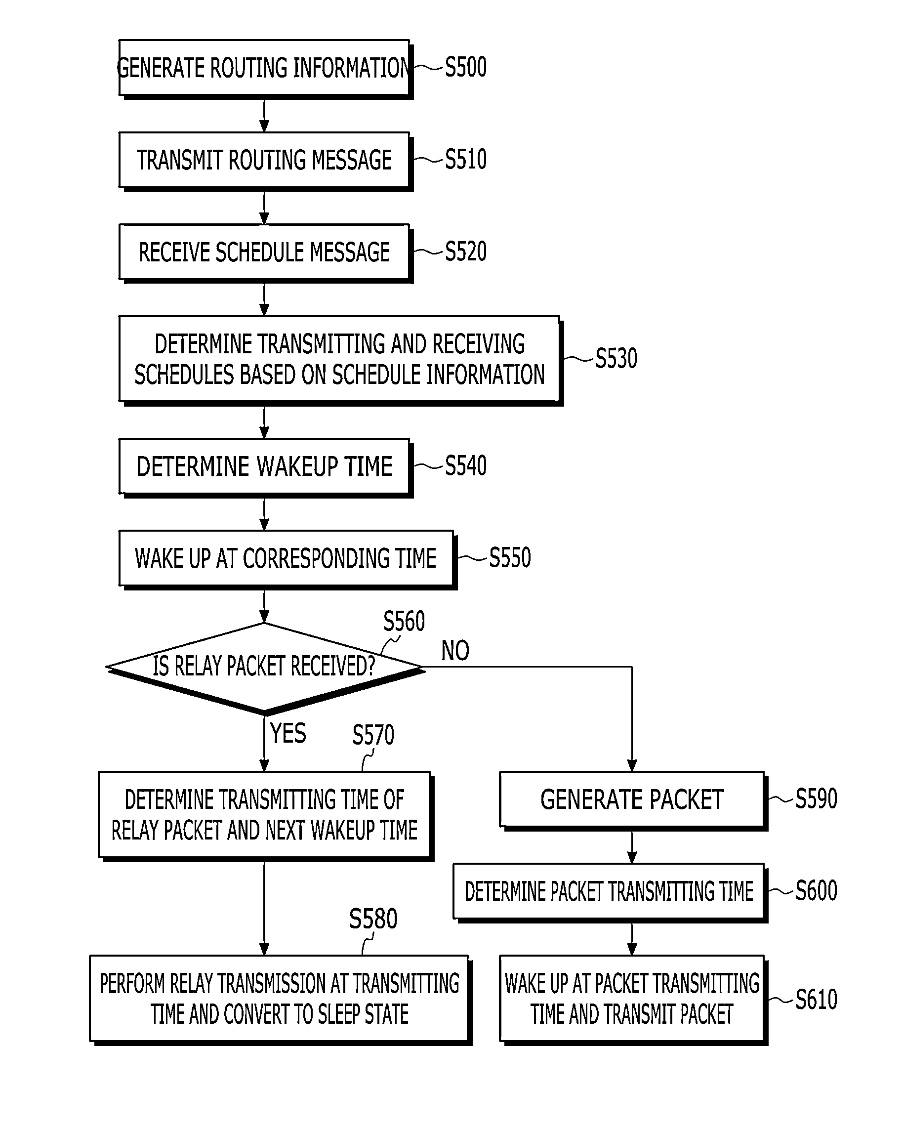
The present invention provides a method and apparatus for transmission scheduling in a wireless sensor network that reduces delivery latency and reduces the load applied to junction nodes. This is achieved by minimizing multi-hop relay transmission and optimizing data transmission paths.

Problems solved by technology

However, because a method of using an idle-listening time is very inefficient, in a wireless sensor network in which energy consumption becomes an important point, further improved media access control (MAC) protocols are required.
However, a MAC protocol of such a typical wireless sensor network is focused and designed in a direction that reduces energy consumption and thus has much limitation.
A typical limitation is an increase of end-to-end delivery latency.
Further, in the S-MAC, because a node is almost simultaneously woken up while being synchronized with an adjacent node, a possibility in which a collision may occur in a network increases.
However, in a wireless sensor network that is specialized for a water environment management, i.e., in a wireless sensor network that is formed with node disposition of a linear form or node disposition of a tree form, optimal scheduling is not performed.
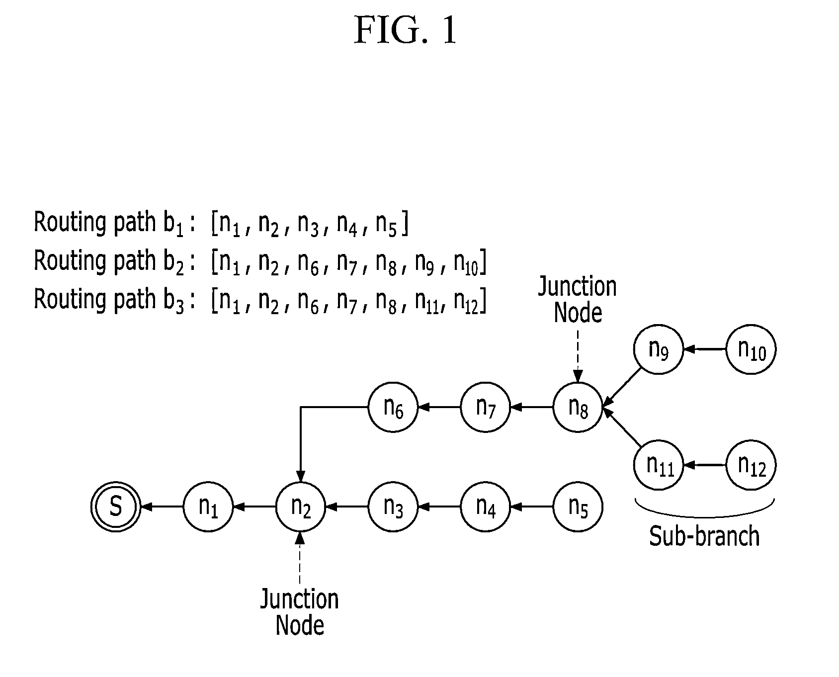
For example, in a water environment management wireless sensor network in which nodes are linearly disposed in a river area or in which nodes are disposed in a tree form at a river junction, information that is sensed in each node is relayed through nodes and is gathered to a sink node, and technology development on a protocol and scheduling algorithm that is optimized for such a network structure are relatively unprepared.

Method used


Image

  • Method and apparatus for transmission scheduling in wireless sensor network
  • Method and apparatus for transmission scheduling in wireless sensor network
  • Method and apparatus for transmission scheduling in wireless sensor network

Examples


Embodiment Construction

[0049]In the following detailed description, only certain exemplary embodiments of the present invention have been shown and described, simply by way of illustration. As those skilled in the art would realize, the described embodiments may be modified in various different ways, all without departing from the spirit or scope of the present invention. Accordingly, the drawings and description are to be regarded as illustrative in nature and not restrictive. Like reference numerals designate like elements throughout the specification.

[0050]In addition, in the entire specification, unless explicitly described to the contrary, the word “comprise” and variations such as “comprises” or “comprising” will be understood to imply the inclusion of stated elements but not the exclusion of any other elements.

[0051]Hereinafter, a method and apparatus for scheduling a packet in a wireless sensor network according to an exemplary embodiment of the present invention will be described with reference t...


PUM


Abstract

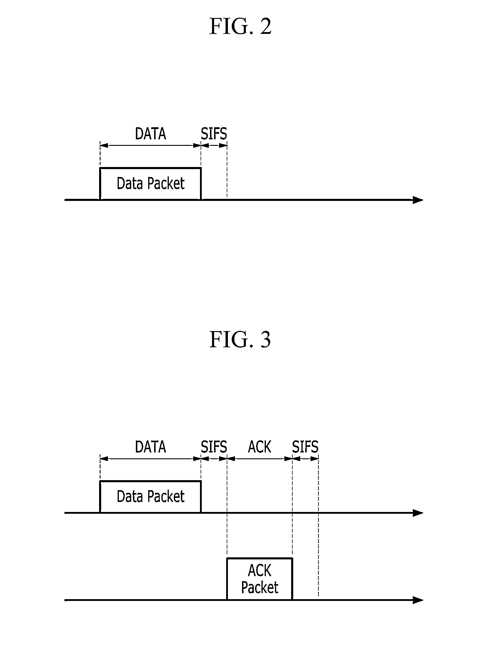
In a sensor network including a sink node and a plurality of sensor nodes, the sink node receives a routing message including routing information from the sensor nodes, analyzes a structure of the sensor network based on routing information, and calculates a transmission schedule of each sensor node based on the analyzed network structure. Schedule information according to the calculated transmission schedule includes a wakeup time of the sensor node, a time interval that is consumed for packet transmission, and a standby time for preventing a packet collision based on the time interval.

Description

CROSS-REFERENCE TO RELATED APPLICATION[0001]This application claims priority to and the benefit of Korean Patent Application No. 10-2013-0092021 filed in the Korean Intellectual Property Office on Aug. 2, 2013, the entire contents of which are incorporated herein by reference.BACKGROUND OF THE INVENTION[0002](a) Field of the Invention[0003]The present invention relates to a method and apparatus for transmission scheduling in a sensor network.[0004](b) Description of the Related Art[0005]For quick monitoring of a sensing target in a wireless environment management sensor network, fast transmission in which latency is minimized and transmission of accurate sensing information in which interference is minimized is essentially required, and small energy consumption is also required.[0006]In an existing wireless sensor network, sensing information that is formed with a packet of a small size frequently occurs, and in order to transmit / receive the entirety of such sensing information, an ...

Claims


Application Information

Patent Timeline
IPC IPC(8): H04W52/02H04W84/18
CPCH04W84/18H04W52/0216Y02D30/70H04W72/12
Inventor JEONG, HOONKIM, GWAN JOONGCHUNG, JONG MOONHAN, DONGHYUKNAM, SANG-JOON
Owner ELECTRONICS & TELECOMM RES INST
Learn More