Laser probe with a replaceable optic fiber

a laser probe and optic fiber technology, applied in laser surgery, medical science, surgery, etc., can solve the problems of increasing treatment costs of single-use laser probes and disposable laser probes

Active Publication Date: 2015-02-05
KATALYST SURGICAL
View PDF4 Cites 61 Cited by
  • Summary
  • Abstract
  • Description
  • Claims
  • Application Information

AI Technical Summary

Benefits of technology

[0004]In one or more embodiments, a laser probe with a replaceable optic fiber may comprise a reusable handle having a handle distal end and a handle proximal end, a reusable housing tube having a housing tube distal end and a housing tube proximal end, a reusable handle adapter having a handle adapter distal end and a handle adapter proximal end, a reusable machine adapter having a machine adapter distal end and a machine adapter proximal end, and a replaceable optic fiber. Illustratively, the handle adapter may be configured to interface with the handle proximal end. In one or more embodiments, the machine adapter may be configured to interface with a surgical machine. Illustratively, the replaceable optic fiber...

Problems solved by technology

Unfortunately, use of disposable, single-use laser probes increases trea...

Method used


Image

  • Laser probe with a replaceable optic fiber
  • Laser probe with a replaceable optic fiber
  • Laser probe with a replaceable optic fiber

Examples


Embodiment Construction

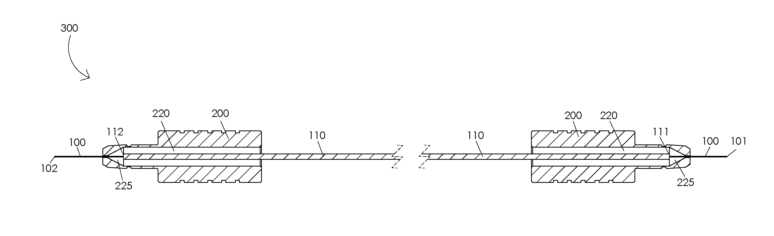
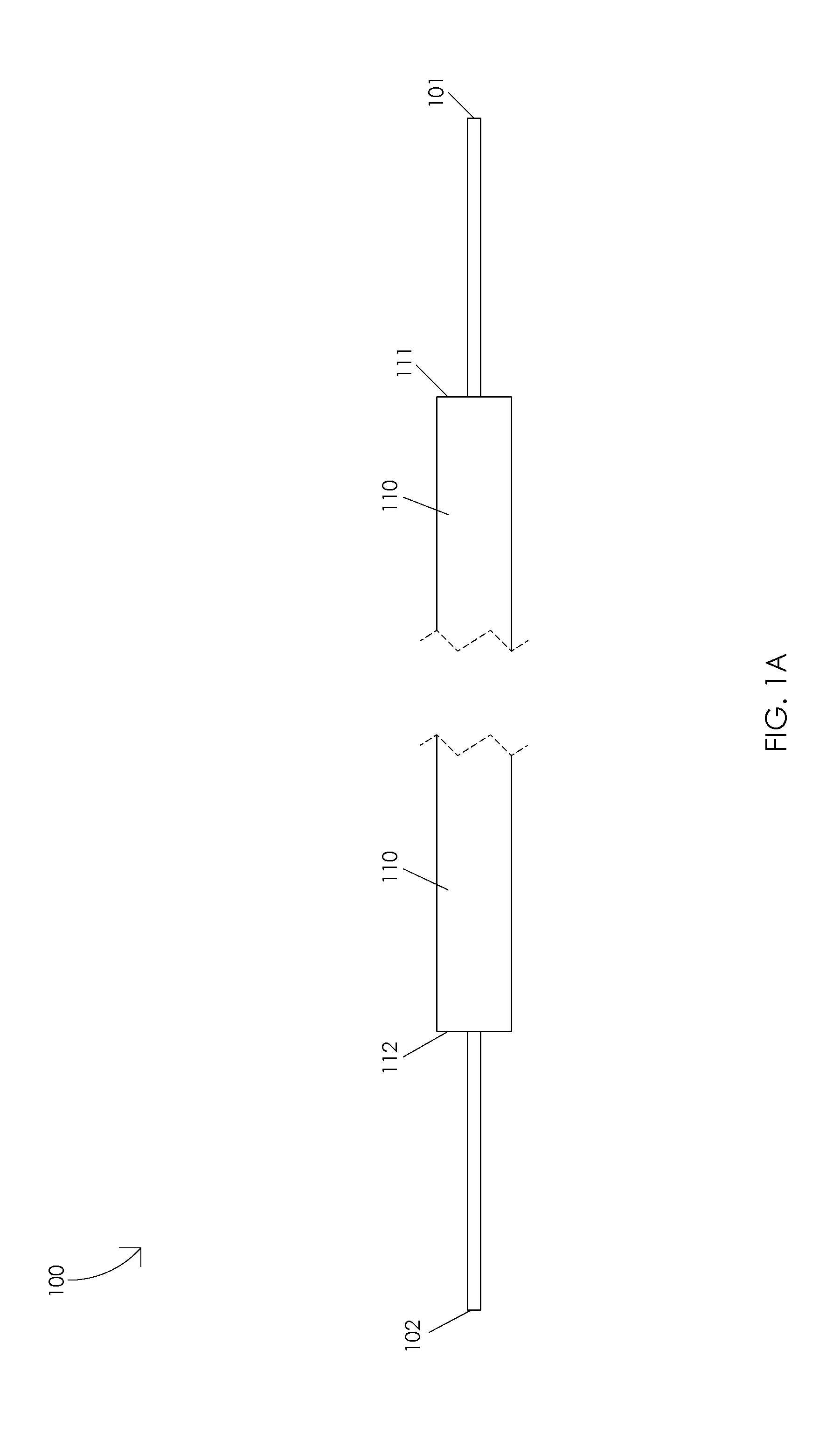
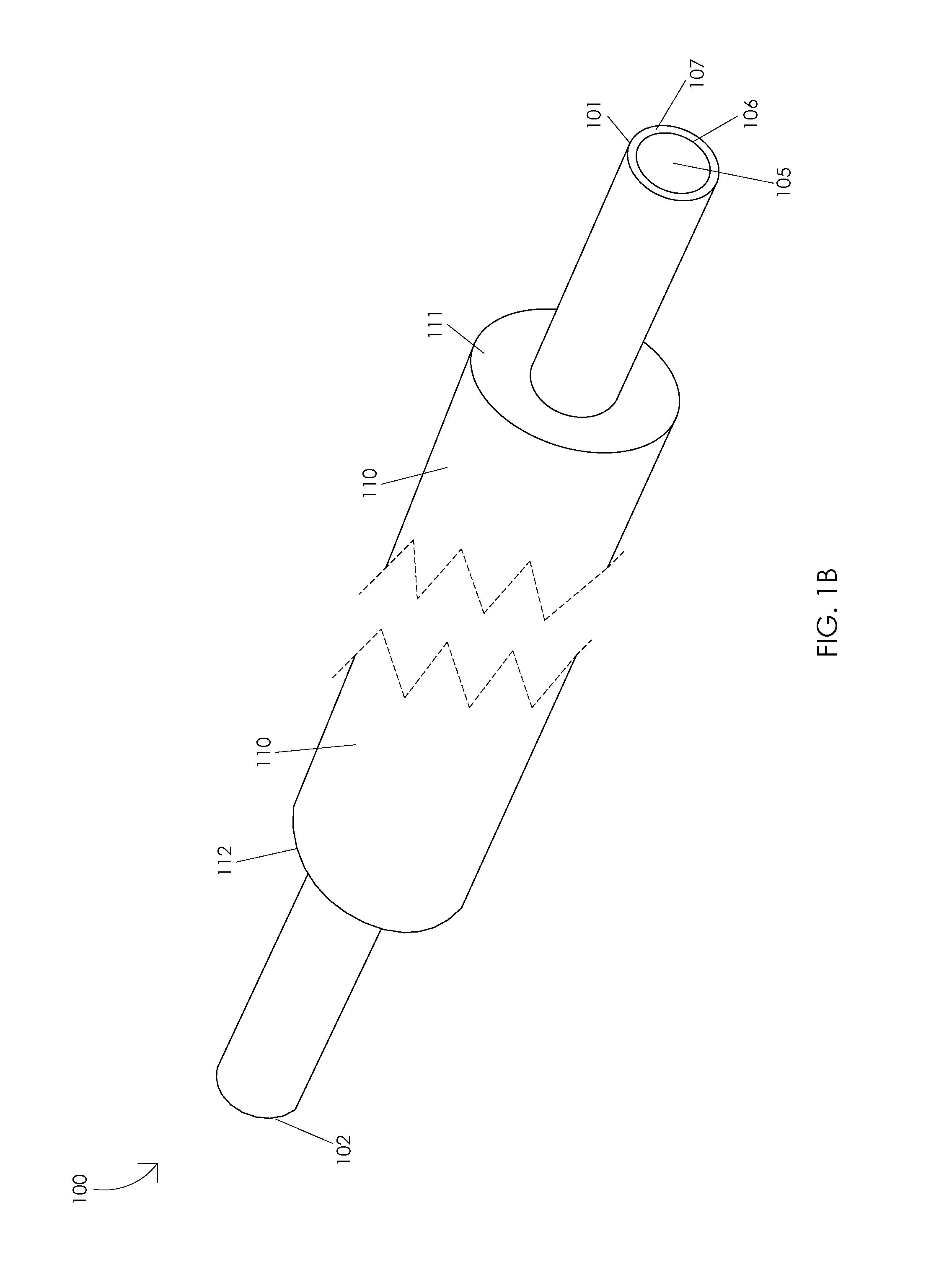
[0023]is FIGS. 1A and 1B are schematic diagrams illustrating an optic fiber 100. FIG. 1A illustrates a side view of optic fiber 100. Illustratively, optic fiber 100 may comprise an optic fiber distal end 101 and an optic fiber proximal end 102. FIG. 1B illustrates an angled view of optic fiber 100. In one or more embodiments, optic fiber 100 may comprise a core 105, a cladding 106, a buffer 107, and a jacket 110 having a jacket distal end 111 and a jacket proximal end 112. Illustratively, at least a portion of core 105 may be disposed in cladding 106. In one or more embodiments, at least a portion of cladding106 may be disposed in buffer 107. Illustratively, at least a portion of buffer 107 may be disposed in jacket 110.

[0024]In one or more embodiments, jacket 110 may be configured to protect a portion of optic fiber 100. Illustratively, jacket 110 may be configured to prevent damage to one or more properties of optic fiber 100, e.g., jacket 110 may be configured to prevent damage t...


PUM


Abstract

A laser probe with a replaceable optic fiber may include a reusable handle, a reusable housing tube, a reusable handle adapter, a reusable machine adapter, and a replaceable optic fiber. The handle adapter may interface with a proximal end of the handle. The machine adapter may interface with a surgical machine. The replaceable optic fiber may include an optic fiber having a first optic fiber end and a second optic fiber end, a first connector, and a second connector. The optic fiber may be disposed within the first connector and the second connector. The first connector may be temporarily fixed within the handle adapter and the second connector may be temporarily fixed within the machine adapter.

Description

CROSS-REFERENCE TO RELATED APPLICATIONS[0001]This application claims the benefit of U.S. Provisional Application No. 61 / 860,482, filed Jul. 31, 2013.FIELD OF THE INVENTION[0002]The present disclosure relates to a surgical instrument, and, more particularly, to a laser probe with a replaceable optic fiber.BACKGROUND OF THE INVENTION[0003]A wide variety of ophthalmic procedures require a laser energy source. For example, ophthalmic surgeons may use laser photocoagulation to treat proliferative retinopathy. Proliferative retinopathy is a condition characterized by the development of abnormal blood vessels in the retina that grow into the vitreous humor. Ophthalmic surgeons may treat this condition by energizing a laser to cauterize portions of the retina to prevent the abnormal blood vessels from growing and hemorrhaging. Typically, treatments are performed using a disposable, single-use laser probe connected to a laser surgical machine by an optical fiber. Unfortunately, use of dispos...

Claims


Application Information

Patent Timeline
IPC IPC(8): A61F9/008
CPCA61F9/008A61F9/00821A61F2009/00863A61F9/00823
Inventor SCHELLER, GREGG D.ZEID, MATTHEW N.
Owner KATALYST SURGICAL
Why Eureka
Try Eureka