

Support Member For Mounting Photovoltaic Modules and Mounting System Including the Same
- Summary
- Abstract
- Description
- Claims
- Application Information
AI Technical Summary
Benefits of technology
Problems solved by technology
Method used
Image

Examples
first embodiment
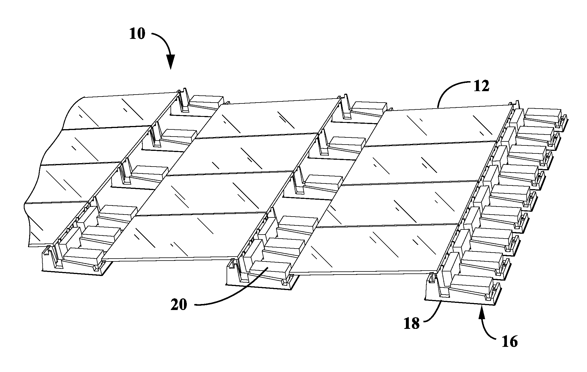
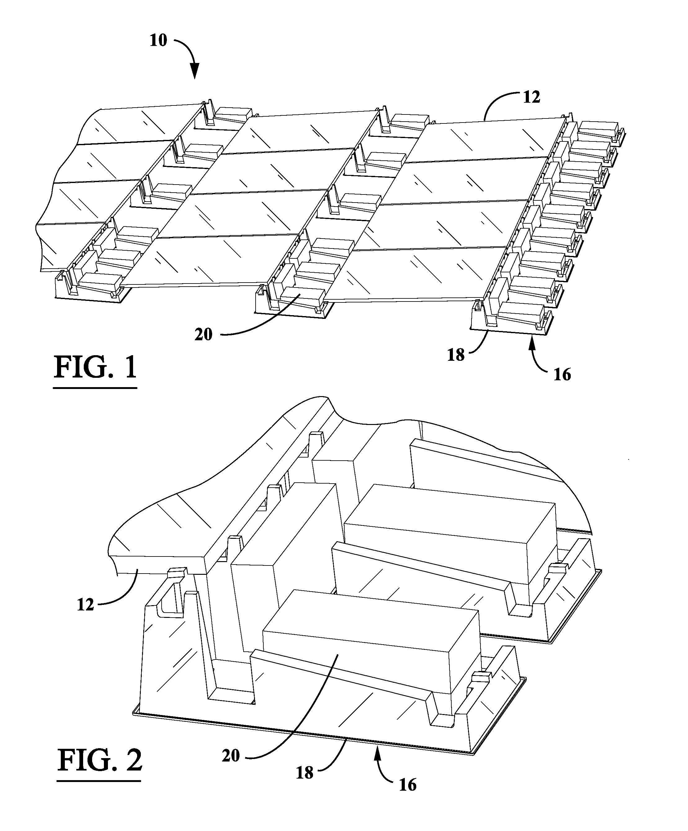
[0049]FIGS. 1 and 2 illustrate a photovoltaic system 10 according to the present invention. The illustrated photovoltaic system or array 10 includes an array of solar panels or PV modules 12 mounted to a substantially flat support surface 14 (pitch range of about 0 degrees to about 5 degrees—see e.g., FIG. 6) in the form of a building rooftop 14 by a mounting system or assembly 16 according to the present invention. The illustrated mounting system 16 includes a plurality of support members 18 that rest on the support surface 14 and support and orient the PV modules 12 above the support surface 14 and a plurality of ballasts 20 in the form of ballast blocks that weight the support members 18 to the support surface 14 to maintain the position of the support members 18 on the support surface 14. The illustrated PV array 10 has each of the rectangular shaped PV modules 12 oriented in a portrait orientation, that is, with the longest axis of the PV modules 12 extending in a forward-rearw...
third embodiment
[0064]FIGS. 9 to 12 illustrate a PV array 10 according to the invention. This embodiment also illustrates that the support members 18 can have other suitable forms. The support member 18 of this embodiment is formed so that the ballast 20, which is in the form of a concrete block, can lay flat in a transverse direction centrally on the support member 18. The support member 18 also does not have the abutment forming walls so that the lower flange 24 of the PV modules can rest on the support surfaces 54, 56 and are secured to the support member 18 by the attachment system 21 in the form of a clamp assembly 80. The illustrated clamp assembly 80 (see FIG. 12) includes a threaded stud or bolt 82 that vertically extends through an opening 84 at the support surface 54, 56. A clamping element 86 is secured to the bolt 82 with a nut 88 to form a compression clamp which secures the PV module 12 to the engagement surface 54, 56 of the support member 18 and the clamping element 86. The illustra...
fourth embodiment
[0070]FIGS. 14-16 illustrate a photovoltaic system or array 100 according to the present invention. As described above for the preceding embodiments, the illustrated photovoltaic system or array 100 includes an array of solar panels or PV modules 102 mounted to a substantially flat support surface 108 (see FIG. 16) in the form of a building rooftop 108 by a mounting system or assembly 110. In FIG. 14, there are two rows of PV modules 102 illustrated for exemplary purposes, each of the two rows having three (3) PV modules 102 disposed therein. The illustrated mounting system 110 includes a plurality of support assemblies 112 (or support assembly members 112) that rest on the support surface 108 and support and orient the PV modules 102 above the support surface 108 and a plurality of ballasts 114 in the form of ballast blocks that weight the support assemblies 112 to the support surface 108 to maintain the position of the support assemblies 112 on the support surface 108. As shown in...
PUM
 Abstract
Description
Claims
Application Information