

Tidal Current Generating Device and Installation Frame Thereof
a technology of current generation and installation frame, which is applied in the direction of water-power plants, electric generator control, machines/engines, etc., can solve the problems of low efficiency, no general-purpose and proven devices are available, and energy needs to be low-carbon, etc., and achieve high power generation efficiency and convenient installation
- Summary
- Abstract
- Description
- Claims
- Application Information
AI Technical Summary
Benefits of technology
Problems solved by technology
Method used
Image

Examples
first embodiment
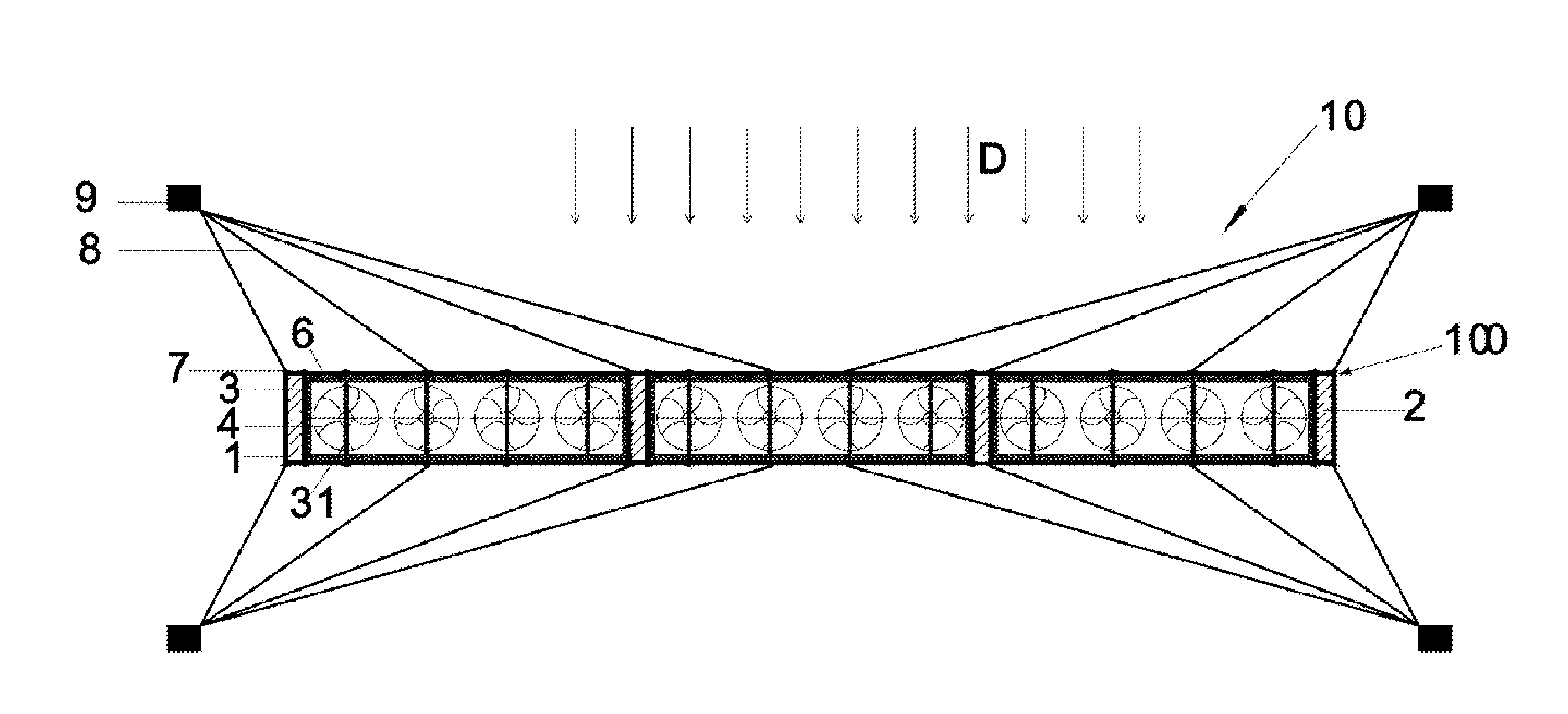
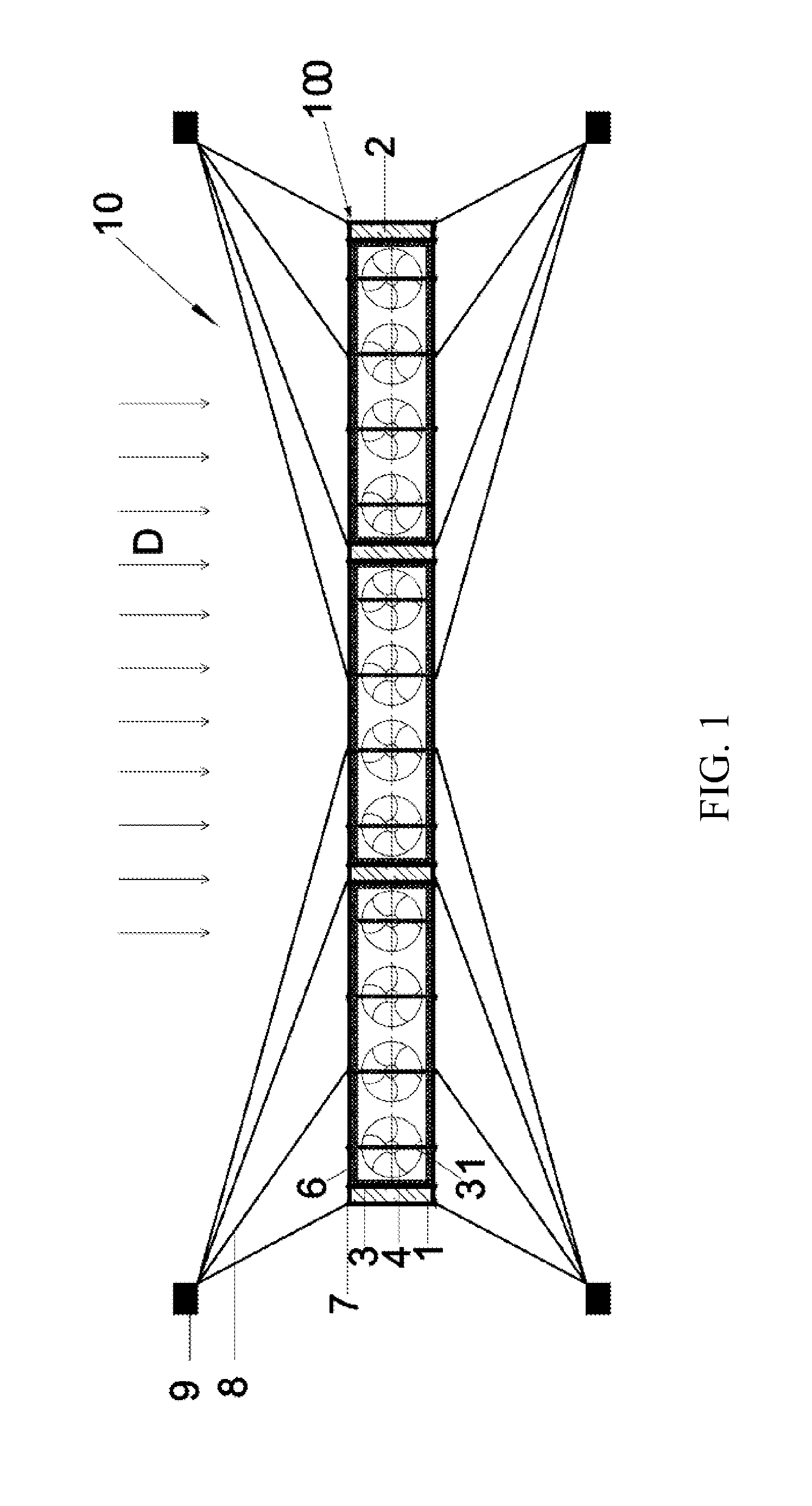
[0039]In the first embodiment, half of the outer frame 1 is formed of hollow steel tubes welded together, while the other half is formed of H-shaped steel. Specifically, the upper half of the outer frame 1 is formed of hollow steel tubes welded together. Thus, the outer frame 1 is light in weight, simply structured, easy to process and manufacture, convenient to install, adjust and dismantle, and suitable for engineering applications. Meanwhile, the outer frame 1 can provide buoyancy to the entire tidal current generating device. In addition, the lower half of the outer frame 1 may be formed of H-shaped steel to ensure that the center of gravity of the outer frame 1 falls into the lower half in order to guarantee the stability of the entire outer frame 1.
[0040]The at least two buoy units 2 are disposed on two sides of the outer frame 1. When the installation frame 100 of the tidal current generating device is used, the at least two buoy units 2 are vertical to a horizontal plane P a...
second embodiment
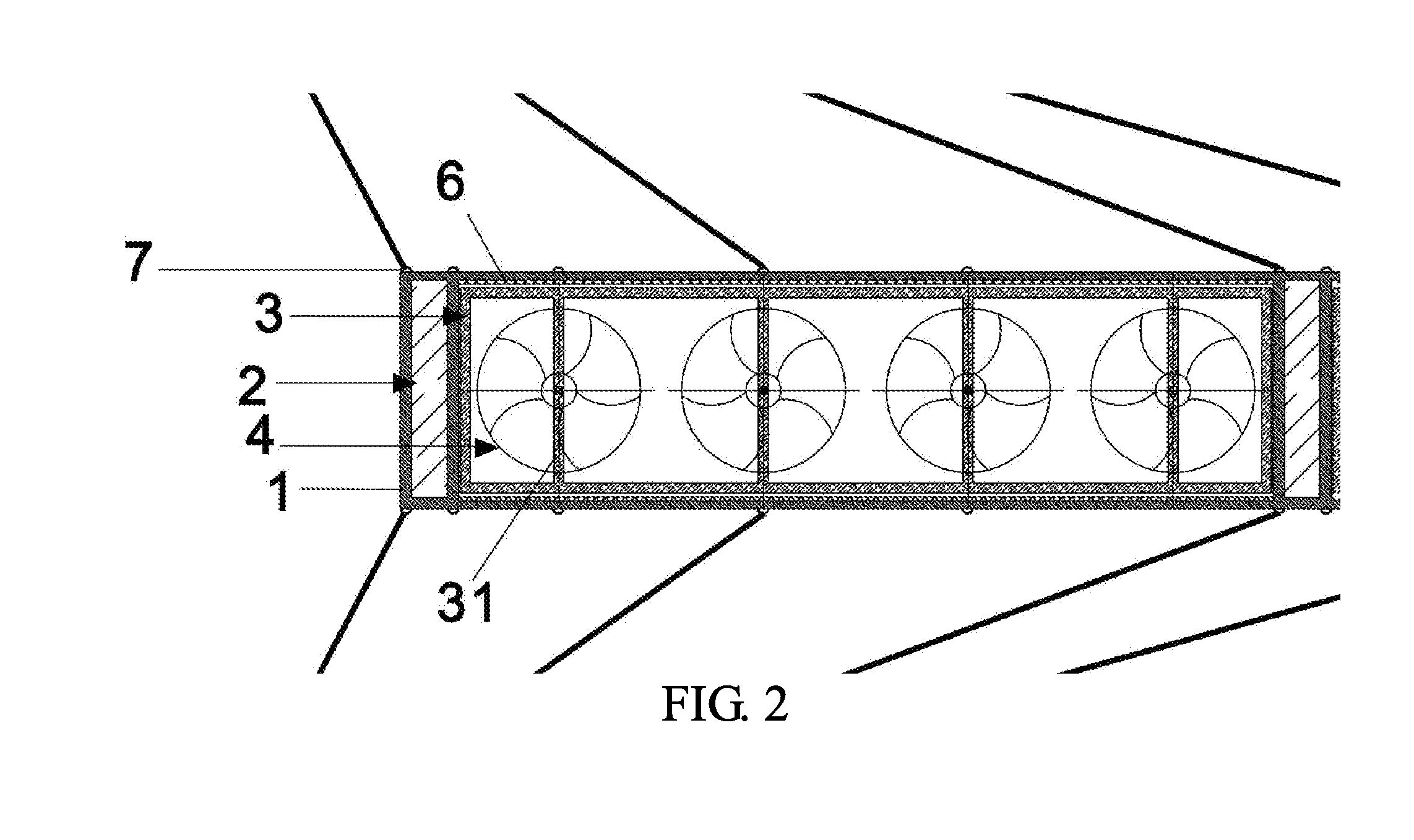
[0055]In the second embodiment, only one hydro turbine 4′ is disposed in each inner frame 3. The tidal current generating device 20 has at least three inner frames 3, that is, includes at least three hydro turbines 4′. In this embodiment, there are six inner frames 3 and six hydro turbines 4′.
[0056]In the second embodiment, the hydro turbines 4′ are horizontal-axis hydro turbines, i.e. the axial direction A2 of the hydro turbines 4′ is parallel to the horizontal plane P. The tidal current generating device 20 further includes a rotating shaft 201 and a drive unit 202. The rotating shaft 201 is rotatably disposed at the inner frame 3. The drive unit 202 is connected with the rotating shaft 201 to drive the rotating shaft to rotate. In this embodiment, the hydro turbines 4′ may be one of turbines with two impellers, turbines with three impellers and turbines with four impellers or any combination thereof.
[0057]In this embodiment, the drive unit 202 includes a motor 2021 and a reducer ...
third embodiment
[0061]In the third embodiment, the number of the hydro turbines 4′ is twice the number of the rotating shafts 201, that is, each rotating shaft 201 is fixed with two hydro turbines 4′. Two hydro turbines 4′ are disposed in each inner frame 3. However, the invention is not limited thereto. In other embodiments, each rotating shaft 201 may be fixed with more than three hydro turbines 4′.
[0062]In conclusion, the installation frame of the tidal current generating device in the invention has buoy units to provide buoyancy to the entire frame, such that the entire installation frame can float near the sea level, thereby using the tidal current occurring near the top of the sea effectively.
[0063]The tidal current generating device in the invention includes at least three hydro turbines distributed in array. Therefore, by the tidal current generating device with the frame provided by the invention, higher power generation efficiency may be achieved without any extremely large hydro turbines...
PUM
 Abstract
Description
Claims
Application Information