Rotor of built-in permanent magnet motor and built-in permanent magnet motor using same

rotor technology, applied in the direction of dynamo-electric machines, magnetic circuit rotating parts, magnetic circuit shapes/forms/construction, etc., can solve the problems of increasing the difficulty of machining a permanent magnet motor, difficult to ensure that the stator and the rotor are coaxial, etc., to achieve convenient and simple machining, reduce the fluctuation of the torque of the interior permanent magnet motor, and great tolerance

Inactive Publication Date: 2015-02-12
DANFOSS (TIANJIN) CO LTD
View PDF4 Cites 3 Cited by
  • Summary
  • Abstract
  • Description
  • Claims
  • Application Information

AI Technical Summary

Benefits of technology

[0023]In a permanent magnet motor, the strength of the torque fluctuations may affect operation performance of the permanent magnet motor, and may be optimized when designing the permanent magnet motor. In the embodiments of the present invention, torque fluctuations of the interior permanent magnet motor is lessen by way of changing distribution of air-gap flux density by changing rotor magnetic resistance of the interior permanent magnet motor. Compared with the conventional way of using an uneven air gap, the embodiments of the present invention have advantages, such as convenient and simple machining and great tolerance, and an advantage of reducing difficulty of making the stator and the rotor coaxially during assembly.

Problems solved by technology

However, this may increase difficulty of machining a permanent magnet motor to some extent, and this may also make it difficult to ensure that the stator and the rotor are coaxial during assembly of the permanent magnet motor.

Method used


Image

  • Rotor of built-in permanent magnet motor and built-in permanent magnet motor using same
  • Rotor of built-in permanent magnet motor and built-in permanent magnet motor using same
  • Rotor of built-in permanent magnet motor and built-in permanent magnet motor using same

Examples


Embodiment Construction

[0029]The technical solution of the present invention will be further described below in detail with reference to embodiments and FIGS. 1-4. In the specification, the same or similar reference signs represent the same or similar components. The following description about the embodiments of the present invention with reference to the accompanying drawings aims to explain the general inventive concept of the present invention, but should not be construed as a limitation to the scope of the present invention.

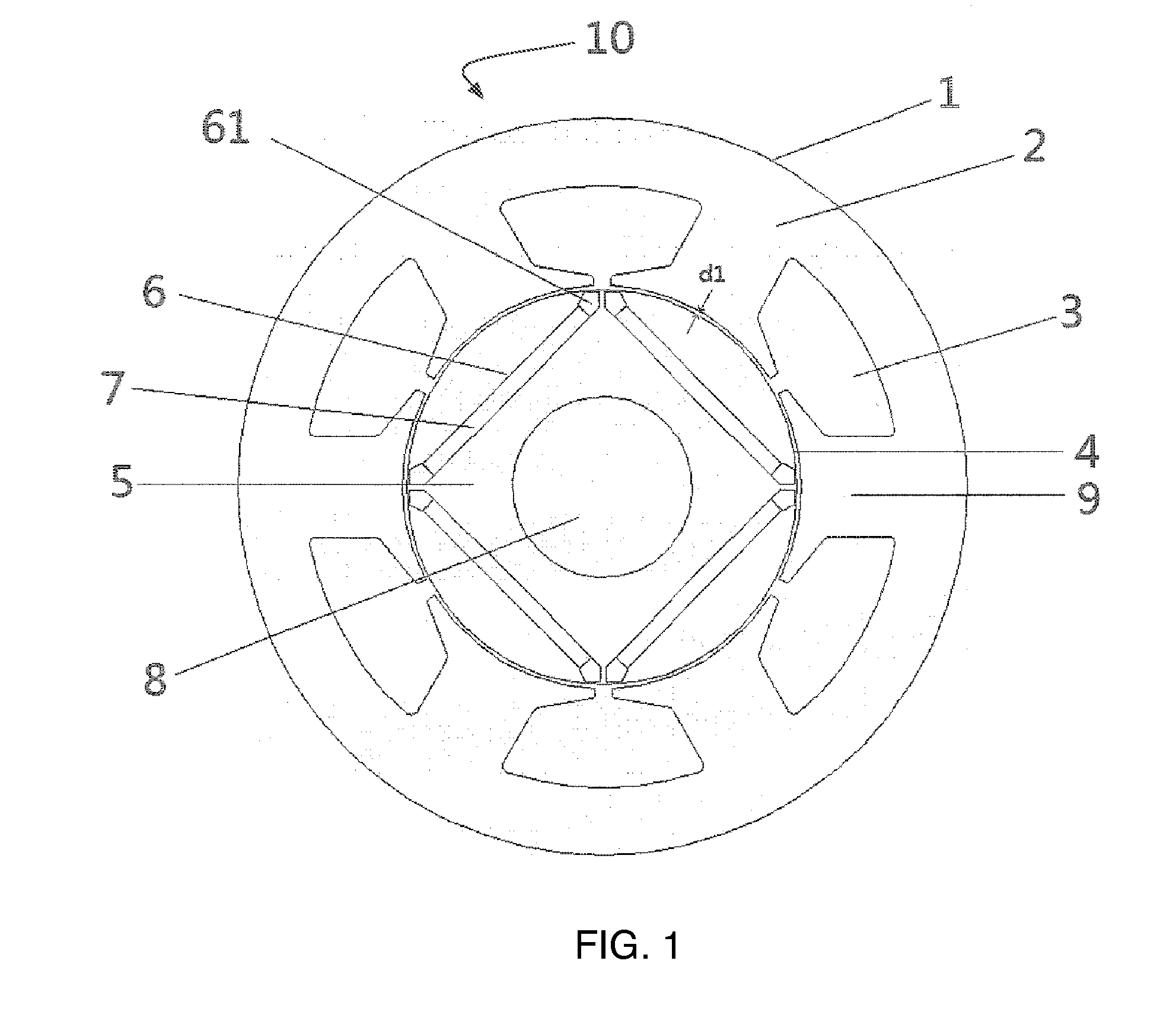
[0030]FIG. 1 is a cross-sectional view of a traditional interior permanent magnet motor 10. The interior permanent magnet motor 10 includes: a stator 1, a coil (not shown in FIG. 1) winding the stator 1 and a rotor 4. The rotor 4 is rotatably disposed in the stator 1.

[0031]The stator 1 includes: a cylindrical stator iron core 2 formed by a plurality of silicon steel sheets laminated together; stator teeth 9 formed in the stator iron core 2 and extending inwards along a radial dire...


PUM


Abstract

A rotor (24) of an interior permanent magnet motor and an interior permanent magnet motor (20) are disclosed. The rotor (24) of the interior permanent magnet motor includes a rotor iron core (25); a plurality of permanent magnets (27), where the plurality of permanent magnets (27) are spaced apart inside the rotor iron core (25); and a plurality of air slots (30), disposed at end portions of adjacent permanent magnets (27) and close to an outer circumference of the rotor, and adapted to generate air gap flux density between the outer circumference of the rotor and an inner circumference of a stator of the interior permanent magnet motor, and the air gap flux density being in an analogous sinusoidal shape.

Description

CROSS-REFERENCE TO RELATED APPLICATION[0001]This application is entitled to the benefit of and incorporates by references subject matter disclosed in International Patent Application No. PCT / CN2012 / 085164, filed on Nov. 23, 2012 and Chinese Patent Application No. 201110380616.2 filed on Nov. 25, 2011.FIELD OF THE INVENTION[0002]The present invention relates to the field of permanent magnet motors, and more particularly to a rotor of an interior permanent magnet motor and an interior permanent magnet motor using the rotor.BACKGROUND[0003]Generally, a permanent magnet motor such as a brushless Direct Current (DC) motor has permanent magnets installed on the core part of a rotor to generate a rotational driving force. Based on the way of installing the permanent magnets on the core part of the rotor, the permanent magnet motor may be a surface-mounted permanent magnet motor or an interior permanent magnet motor.[0004]Typically, an interior permanent magnet motor has a plurality of perm...

Claims


Application Information

Patent Timeline
Patent Type & Authority Applications(United States)
IPC IPC(8): H02K1/27
CPCH02K1/276H02K29/03
Inventor YAO, LILIU, WANZHENWANG, ZHENYULIN, YAN
Owner DANFOSS (TIANJIN) CO LTD
Why Eureka
Try Eureka