Light control film, display device, and method for manufacturing light control film

Active Publication Date: 2015-02-12
SHARP KK
View PDF4 Cites 28 Cited by
  • Summary
  • Abstract
  • Description
  • Claims
  • Application Information

AI Technical Summary

Benefits of technology

[0031]According to the present invention, it is possible to provide a light control film, a display device, and a method for m

Problems solved by technology

In relation to performance of the liquid crystal display device, the liquid crystal display device has a good display performance when a display surface is viewed from a front side, but contrast decreases and thus visibility tends to degrade when viewed in an oblique direction.
In addition

Method used


Image

  • Light control film, display device, and method for manufacturing light control film
  • Light control film, display device, and method for manufacturing light control film
  • Light control film, display device, and method for manufacturing light control film

Examples


second embodiment

[0208]Hereinafter, a second embodiment of the present invention will be described with reference to FIGS. 7A to 8F.

[0209]A fundamental configuration of a liquid crystal display device of the present invention is the same as the configuration of the first embodiment, and is different from that of the first embodiment only in that a light scattering body is included in a base material. Therefore, in the present embodiment, description of the fundamental configuration of the liquid crystal display device will be omitted, and only a light control film will be described.

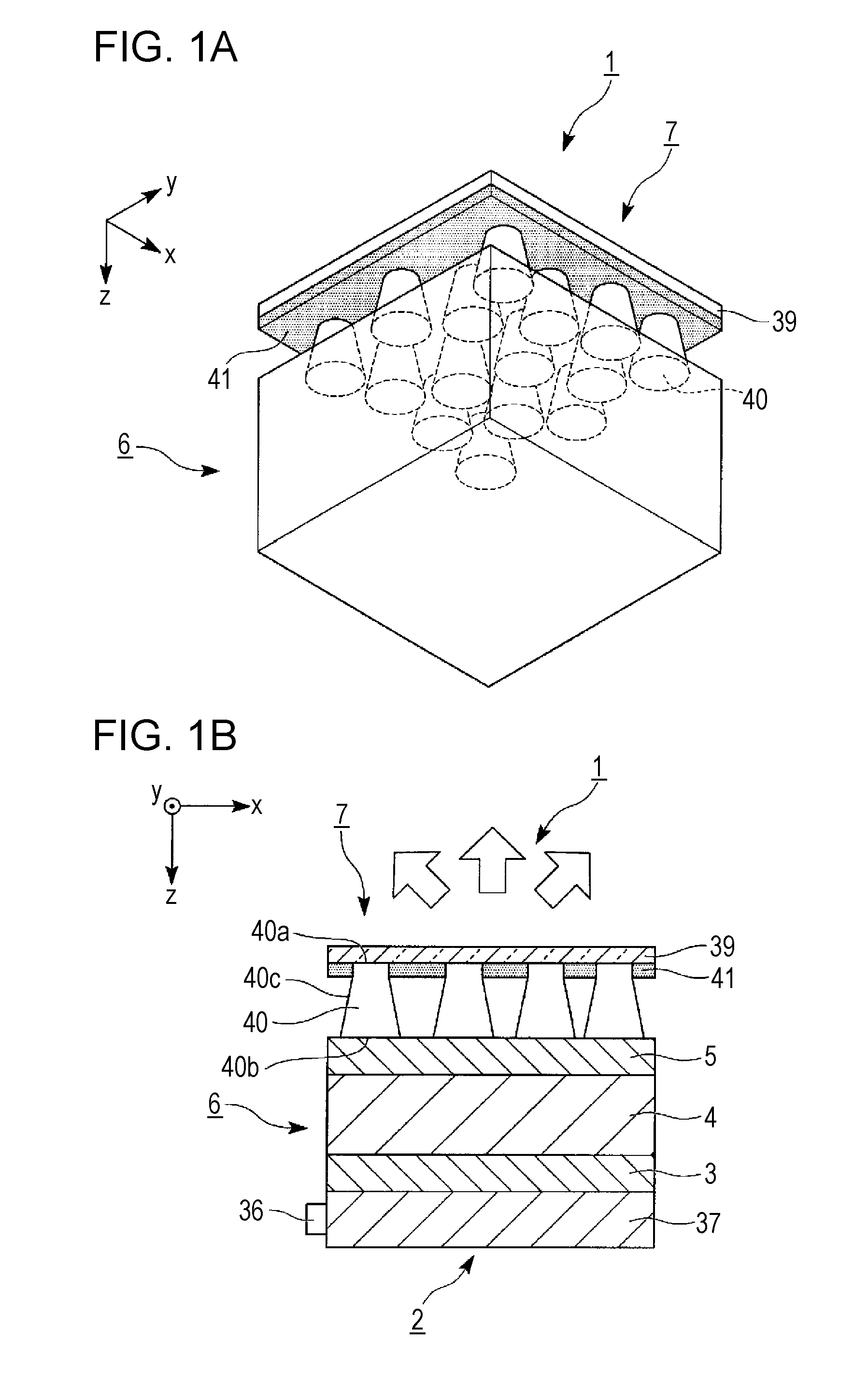
[0210]FIGS. 7A and 7B are schematic diagrams illustrating a liquid crystal display device of the present embodiment. FIG. 7A is a perspective view of a liquid crystal display device 1B of the present embodiment, and FIG. 7B is a cross-sectional view of the liquid crystal display device 1B of the present embodiment.

[0211]FIGS. 8A to 8F are cross-sectional views illustrating a light control film in a manufacturing step orde...

third embodiment

[0228]Hereinafter, a third embodiment of the present invention will be described with reference to FIGS. 9A to 11B.

[0229]A fundamental configuration of a liquid crystal display device of the present invention is the same as the configuration of the first embodiment, and only a configuration of a light diffusion portion of a light control film is different from that of the first embodiment. Therefore, in the present embodiment, description of the fundamental configuration of the liquid crystal display device will be omitted, and only a light control film will be described.

[0230]FIGS. 9A and 9B are schematic diagrams illustrating a liquid crystal display device of the present embodiment. FIG. 9A is a perspective view of a liquid crystal display device 10 of the present embodiment, and FIG. 9B is a cross-sectional view of the liquid crystal display device 10 of the present embodiment.

[0231]FIGS. 10A, 10B, 11A and 11B are diagrams illustrating an operation of a light control film.

[0232]...

fourth embodiment

[0239]Hereinafter, a fourth embodiment of the present invention will be described with reference to FIGS. 12 to 14B.

[0240]A fundamental configuration of a liquid crystal display device of the present invention is the same as the configuration of the first embodiment, and only a shape of a light diffusion portion of a light control film is different from that of the first embodiment. Therefore, in the present embodiment, description of the fundamental configuration of the liquid crystal display device will be omitted, and only a light control film will be described.

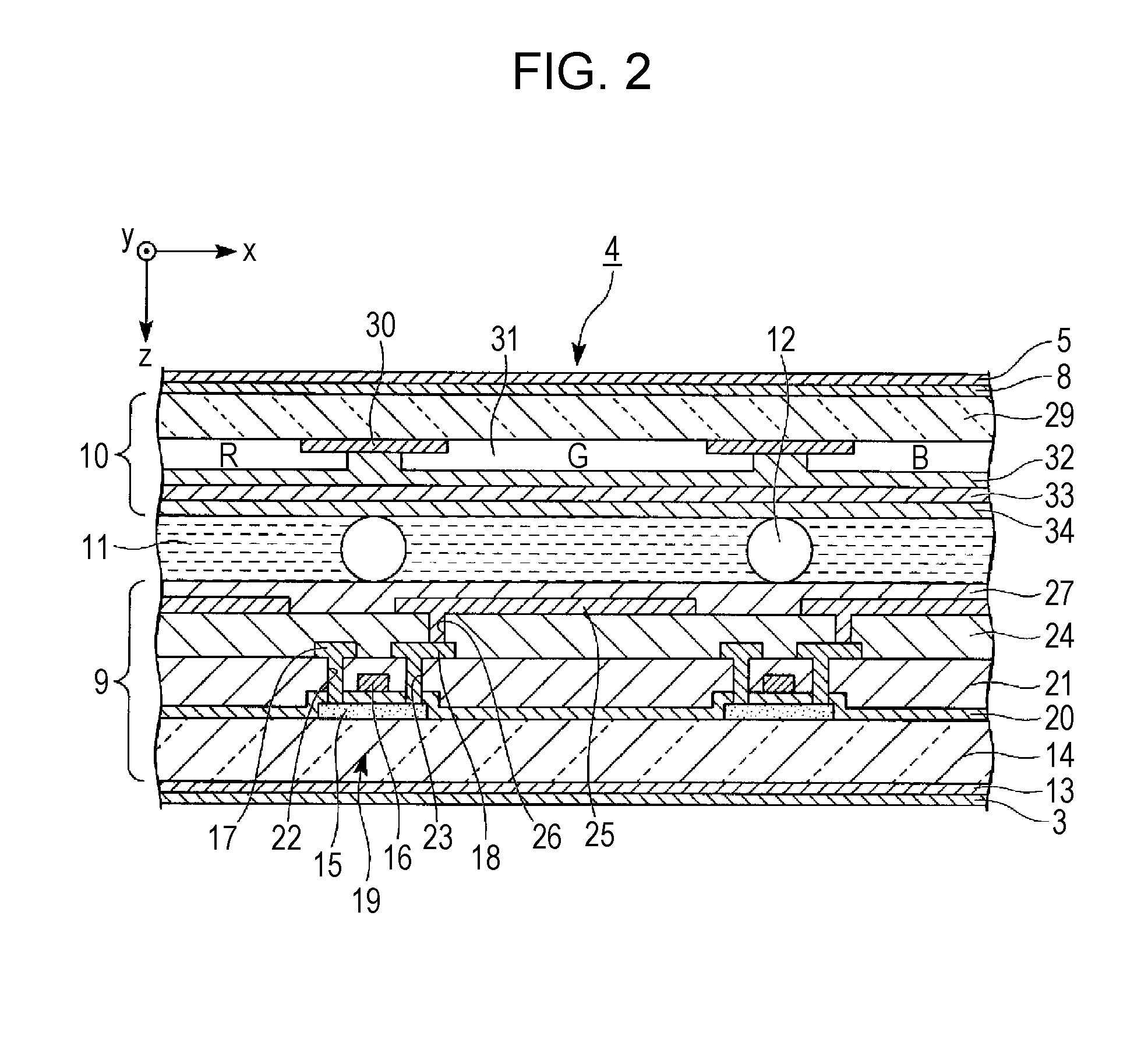
[0241]FIG. 12 is a cross-sectional view illustrating a liquid crystal display device of the present embodiment.

[0242]FIG. 13A is a cross-sectional view of a light control film 7D of the present embodiment, andFIG. 13B is a plan view illustrating a photomask used for manufacturing the light control film.

[0243]FIGS. 14A and 14B are diagrams illustrating a method for manufacturing the light control film of the present embodim...


PUM


Abstract

A light control film includes a light shielding layer and a light diffusion portion, and, when an area of a part where the light shielding layer is in contact with one surface of the base material is set to S1, and an area of a part where a low refractive index portion is exposed between light incidence end surfaces is set to S2, the light shielding layer and the light diffusion portion are formed so as to satisfy (S1−S2)/S1×100≧50.

Description

TECHNICAL FIELD[0001]The present invention relates to a light control film, a display device, and a method for manufacturing the light control film capable of improving display quality by improving contrast.[0002]The present application is based upon and claims the benefit of priority from Japanese Patent Application No. 2012-074766, filed Mar. 28, 2012, the entire contents of which are incorporated herein by reference.BACKGROUND ART[0003]A liquid crystal display device is widely used in a display unit or the like of a thin television set or a mobile phone. In relation to performance of the liquid crystal display device, the liquid crystal display device has a good display performance when a display surface is viewed from a front side, but contrast decreases and thus visibility tends to degrade when viewed in an oblique direction. In addition, there is a case where, in grayscale display, grayscale inversion in which brightness is inverted occurs, and thus a display performance is de...

Claims


Application Information

Patent Timeline
IPC IPC(8): G02F1/1335G03F7/20G02B5/02
CPCG02F1/133504G03F7/20G02B5/0242G02B5/0231G02B5/0236G02B5/0294G02F1/133512G02F1/133562
Inventor YAMAMOTO, EMIMAEDA, TSUYOSHIKANNO, TORU
Owner SHARP KK
Why Eureka
Try Eureka