
Encoding and decoding by selective inheritance

a selective inheritance and encoding technology, applied in the field of signal encoding and decoding, can solve the problems of high cost associated with mvc coding, and achieve the effect of reducing the cost of transmission between the encoder and the decoder

Active Publication Date: 2015-02-12
ORANGE SA (FR)
View PDF4 Cites 8 Cited by
  • Summary
  • Abstract
  • Description
  • Claims
  • Application Information

AI Technical Summary

Benefits of technology

The invention allows for selective inheritance encoding and decoding, which means that information can be inherited either directly or indirectly through a reference block. This reduces the amount of data needed to store the information and prevents the replacement of a predictor with a new predictor when the reference block value is low. The invention also allows for simultaneous consideration of direct and indirect inheritance methods for the same block. These technical effects help improve the efficiency and accuracy of video compression.

Problems solved by technology

However, the cost associated with MVC coding is high, especially when the number of viewpoints is high.

Method used


Image

  • Encoding and decoding by selective inheritance
  • Encoding and decoding by selective inheritance
  • Encoding and decoding by selective inheritance

Examples


Embodiment Construction

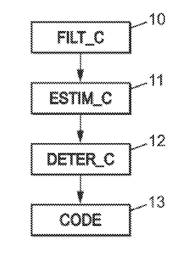
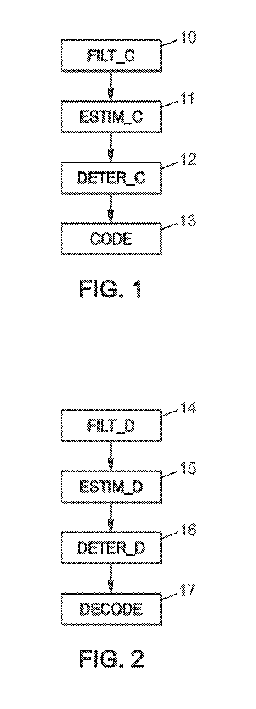
[0090]FIG. 1 is a diagram representing the main steps of an encoding method according to the invention.

[0091]The encoding method according to the invention is applied to a current block of a first image relative to a reference block of a second image comprising at least one element in common with the first image. “Reference block” is understood to mean a block that has been previously encoded and then decoded. Such a decoded reference block is used for coding the current block.

[0092]In step 10, the decoded reference block is filtered.

[0093]Such a step is performed for example using an edge detection filter to detect edges in said decoded reference block. Such a filter may be a Sobel filter, a Canny filter, or some other edge detection filter.

[0094]In step 11, at least one value of a local characteristic of the filtered decoded reference block is estimated by calculation solely on the basis of the decoded reference block.

[0095]Such a local characteristic is for example:[0096]a primar...


PUM


Abstract

A method is provided for decoding at least one current encoded block of a first image relative to a reference block of a second image including at least one common element with the first image, wherein the reference block has been previously decoded. The method includes: filtering the decoded reference block; estimating, only on the basis of the filtered decoded reference block, at least one value of a local characteristic of the filtered decoded reference block; determining, on the basis of the estimated value of the local characteristic: a set of decoding information to be used for decoding the current block, a method for decoding the current block, on the basis of the estimated value of the local characteristic, decoding the current block on the basis of the set of determined decoding information and according to the determined decoding method.

Description

CROSS-REFERENCE TO RELATED APPLICATIONS[0001]This Application is a Section 371 National Stage Application of International Application No. PCT / FR2013 / 050160, filed Jan. 25, 2013, which is incorporated herein by reference in its entirety and published as WO 2013 / 114028 on Aug. 8, 2013, not in English.FIELD OF THE DISCLOSURE[0002]The present invention relates to the field of signal encoding and decoding, and in particular the encoding / decoding of video signals.[0003]It relates in particular, but not exclusively, to 3D video applications that encode / decode images from different cameras. The present application similarly applies to the encoding / decoding of still images.BACKGROUND OF THE DISCLOSURE[0004]A 3D representation of a video can be obtained by multiplexing two views (stereo format) of the same scene, recorded by two different cameras of a single stereoscopic device.[0005]Two types of coding, MFC and MVC (for “Multiview Frame-compatible Coding” and “Multiview Video Coding”) are t...

Claims


Application Information

Patent Timeline
Patent Type & Authority Applications(United States)
IPC IPC(8): H04N19/597H04N19/44
CPCH04N19/44H04N19/597H04N19/103H04N19/157H04N19/197H04N19/51H04N19/52
Inventor JUNG, JOELMORA, ELIE
Owner ORANGE SA (FR)
Learn More