Methods and systems for surge control

a surge control and surge technology, applied in the direction of electric control, machines/engines, combustion engines, etc., can solve the problems of reducing potential surge, and prone to surge, so as to reduce forward flow through the compressor, improve peak power output, and increase fuel economy

Active Publication Date: 2015-02-19
FORD GLOBAL TECH LLC
View PDF5 Cites 18 Cited by
  • Summary
  • Abstract
  • Description
  • Claims
  • Application Information

AI Technical Summary

Benefits of technology

[0005]In one example, some of the above issues may be addressed by a method for a boosted engine comprising: adjusting flow through each of a first higher flow compressor recirculation path and a second lower flow compressor recirculation path based on a throttle mass flow to maintain a compressor flow rate at or above a threshold flow rate, the second recirculation passage positioned in parallel to the first recirculation passage. In this way, a compressor flow rate can be maintained above a flow rate at the hard surge line and compressor operation may be kept outside a surge region during steady-state as well as transient engine operating conditions.
[0007]If the throttle mass flow is higher than the desired (surge constrained) compressor flow rate, one or more of the compressor recirculation valves may be maintained closed. For example, both valves may be held closed to decrease recirculation flow. Alternatively, the first valve may be held closed while the second valve is left open so that a smaller portion of compressor recirculation flow is kept to provide an improved surge margin. If the throttle mass flow suddenly drops (e.g., during a tip-out) or if the steady-state throttle mass flow is lower than the desired compressor flow rate, both valves may be opened to increase the recirculation flow. Alternatively, the first valve may be opened while the second valve is left closed so that there is a larger portion of compressor recirculation flow. In either case, the flow rate through the compressor is increased, improving the surge margin.
[0008]In this way, by adjusting flow through both the compressor recirculation paths based on a throttle mass flow, a compressor flow rate can be kept sufficiently high. This enables compressor operation during steady-state as well as transient operating conditions to remain outside a surge region (e.g., outside a hard surge region and a soft surge region). As such, this allows both hard surge and soft surge to be better addressed. By improving the surge margin under all engine operating conditions, surge related NVH issues and component damage issues are reduced. In addition, soft surge can be addressed without degrading driveability and engine performance.

Problems solved by technology

However, compressors are prone to surge.
For example, when an operator tips-out of an accelerator pedal, an engine intake throttle closes, leading to reduced forward flow through the compressor, and a potential for surge.
As such, surge can lead to NVH issues such as undesirable noise from the engine intake system.
For example, during hard surge, the compressor allows air to momentarily backflow through the compressor resulting in rapid pressure oscillations, while during soft surge, smaller pressure oscillations are experienced.
However the inventors herein have identified potential issues with such an approach.
As one example, the valve of Blaiklock may be ineffective for managing soft surge.
As a result, soft surge is typically not addressed by opening a compressor recirculation valve but by lowering the engine torque curve such that engine operating conditions lie outside of the areas of the compressor map where soft surge tends to occur.
As such, this can lead to compromises in driveability and performance, particularly for highly downsized engine configurations and / or at high altitudes and ambient temperatures.
On the other hand, if a compressor recirculation valve were opened in response to soft surge, driver torque demand could not be maintained.

Method used


Image

  • Methods and systems for surge control
  • Methods and systems for surge control
  • Methods and systems for surge control

Examples


Embodiment Construction

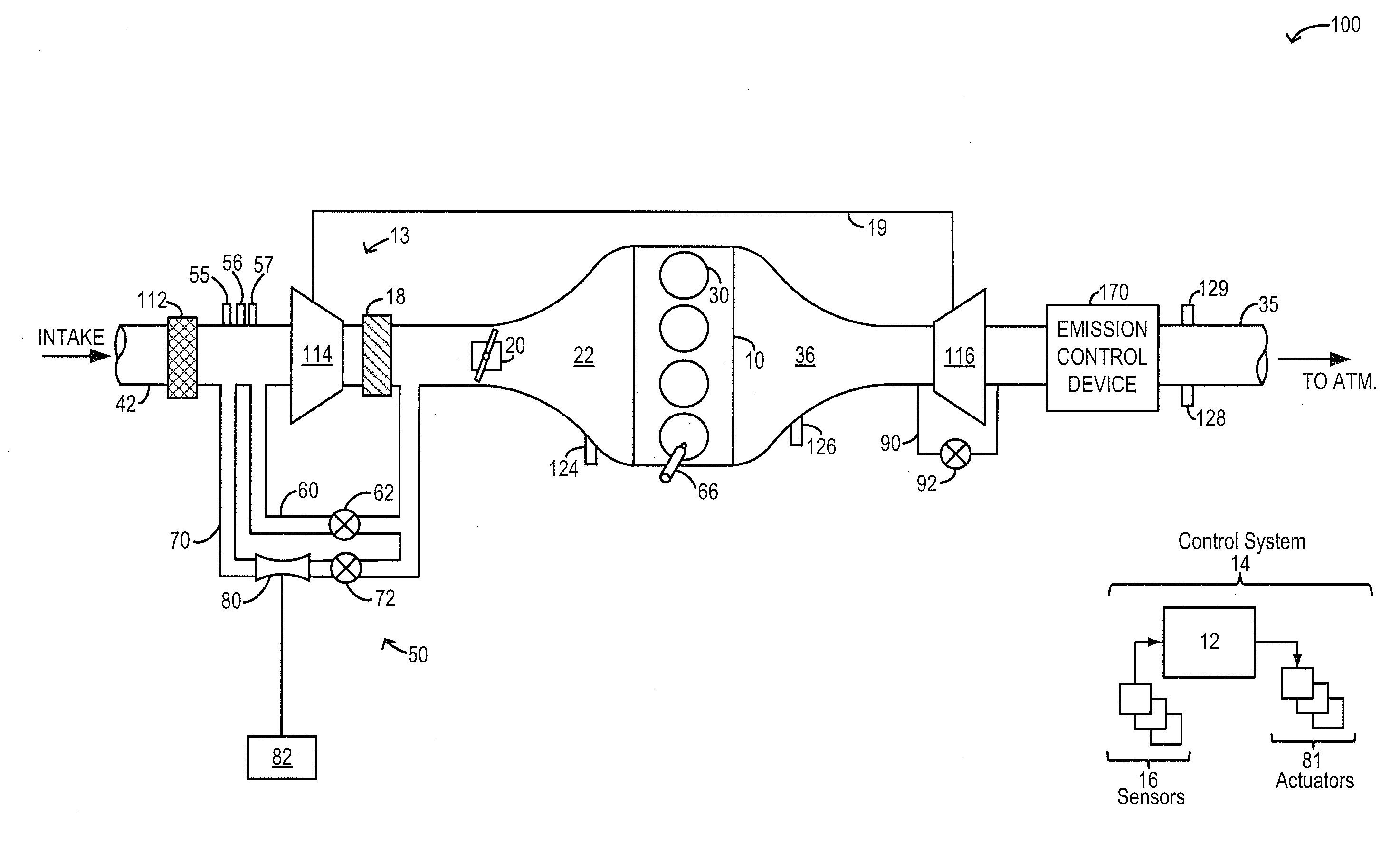
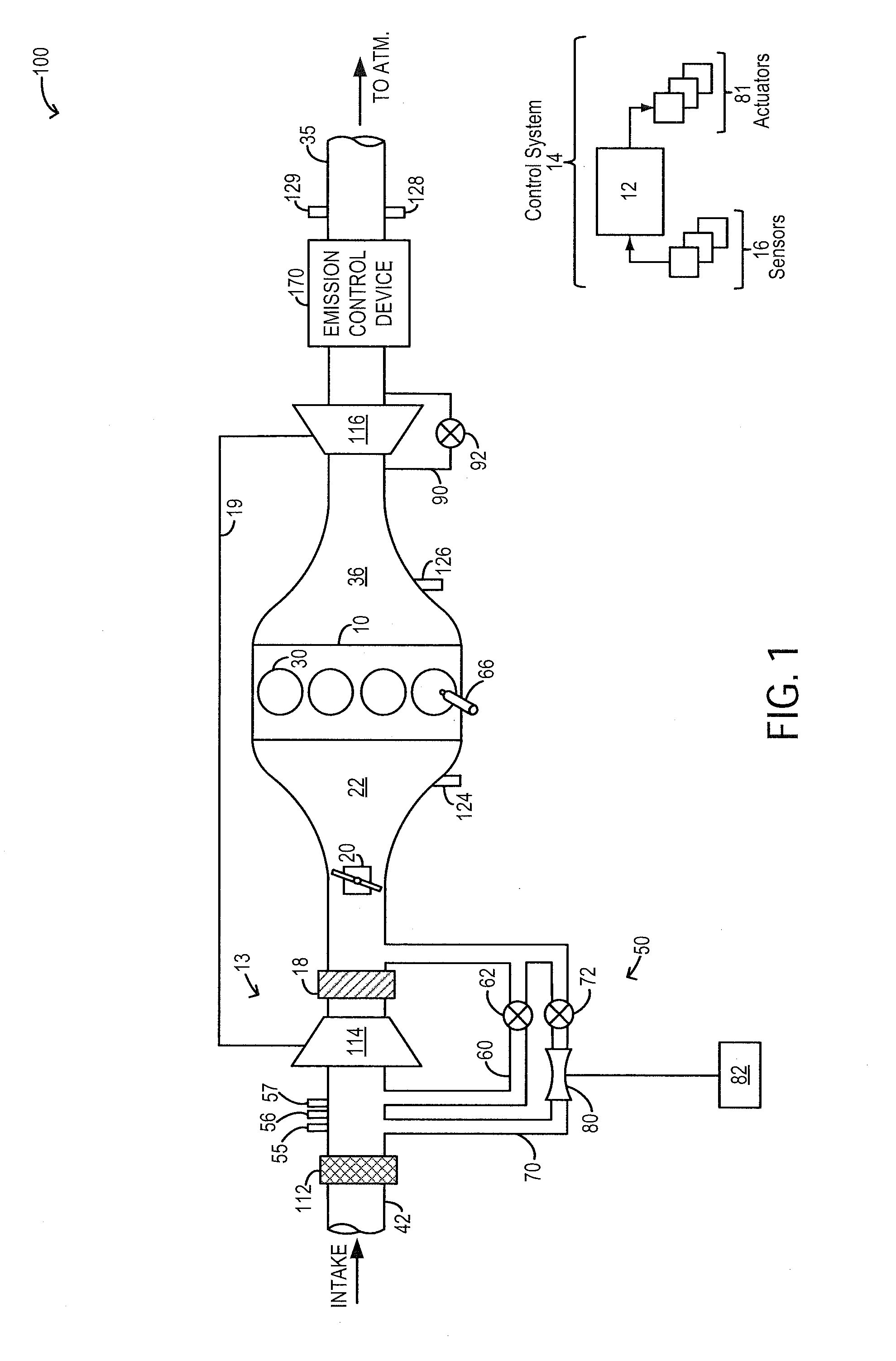
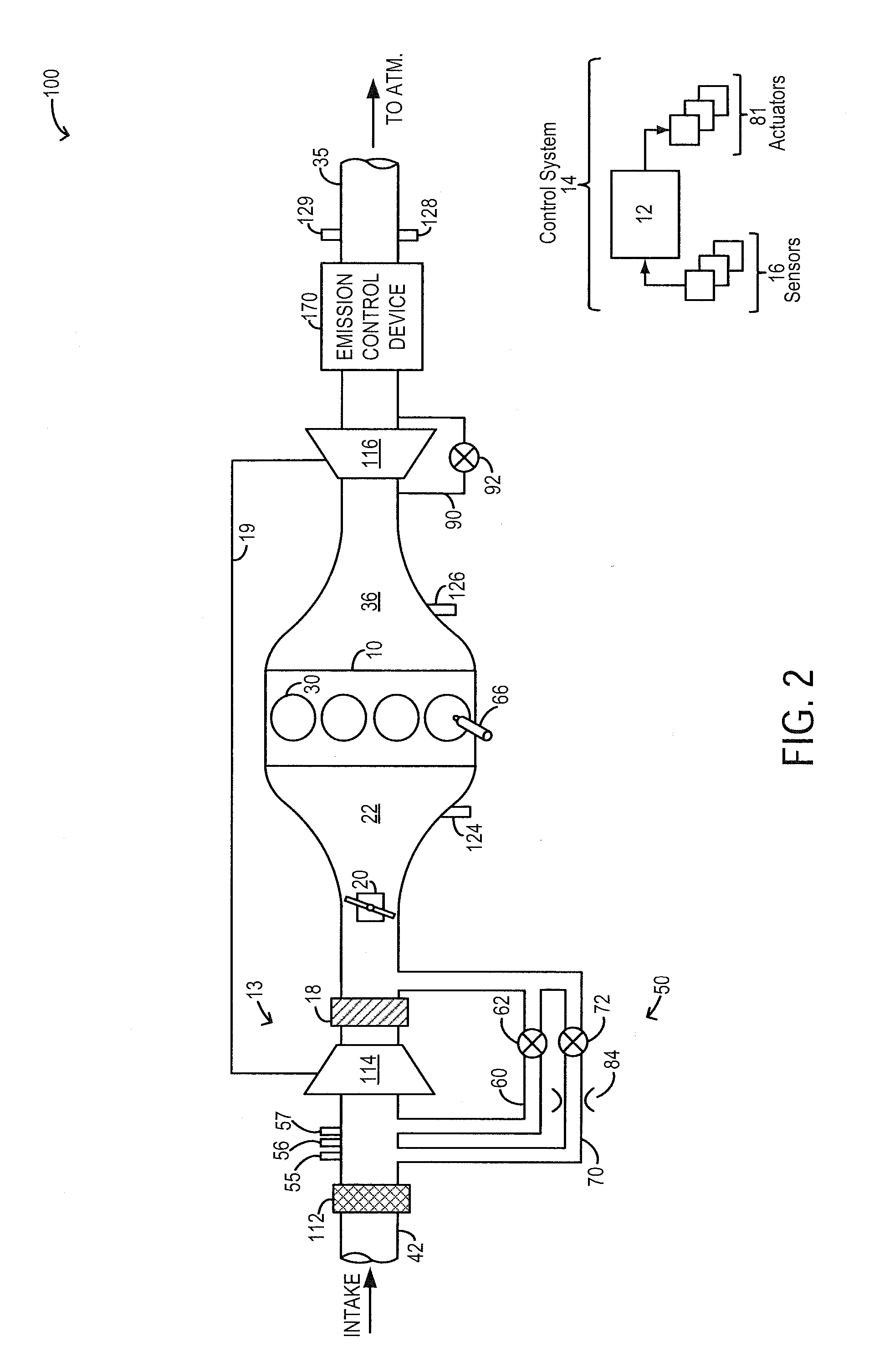
[0014]The following description relates to systems and methods for reducing compressor surge in a boosted engine system, such as the system of FIGS. 1-2. A controller may be configured to perform a control routine, such as the routine of FIG. 4, to adjust compressor recirculation flow through each of a high flow recirculation path and a low flow recirculation path to the compressor inlet. The controller may adjust the position of one or more valves coupled to the recirculation passages based on engine operating conditions and changes to throttle flow to maintain the compressor flow rate at or above a surge constrained flow rate. The controller may refer to a compressor map, such as the map of FIG. 3, to identify hard and soft surge limits and determine surge constrained flow rates at those limits. Example valve adjustments are described with reference to FIG. 5. In this way, a margin to surge is improved.

[0015]FIGS. 1-2 schematically show aspects of an example engine system 100 incl...


PUM


Abstract

Methods and systems are provided for recirculating compressed air across a compressor through a high flow and a low flow compressor recirculation path. Flow through the recirculation paths is controlled via respective valves and valve opening is adjusted based on a throttle mass flow so as to maintain a compressor flow rate at or above a surge constrained flow rate. By maintaining a sufficiently high compressor flow rate during steady state and transient conditions, the compressor state can be maintained outside a surge region.

Description

FIELD[0001]The present application relates to methods and systems for using compressor recirculation flow to improve surge control.BACKGROUND AND SUMMARY[0002]Engine systems may be configured with boosting devices, such as turbochargers or superchargers, for providing a boosted aircharge and improving peak power outputs. The use of a compressor allows a smaller displacement engine to provide as much power as a larger displacement engine, but with additional fuel economy benefits. However, compressors are prone to surge. For example, when an operator tips-out of an accelerator pedal, an engine intake throttle closes, leading to reduced forward flow through the compressor, and a potential for surge. As such, surge can lead to NVH issues such as undesirable noise from the engine intake system. For example, during hard surge, the compressor allows air to momentarily backflow through the compressor resulting in rapid pressure oscillations, while during soft surge, smaller pressure oscill...

Claims


Application Information

Patent Timeline
Patent Type & Authority Applications(United States)
IPC IPC(8): F02D41/00
CPCF02D41/0007F02B37/164F02B2037/125F02D41/10F02D41/18F02B37/162Y02T10/12
Inventor BUCKLAND, JULIA HELENWADE, ROBERT ANDREWMCCONVILLE, GREGORY PATRICKPAYNE, KEVINULREY, JOSEPH
Owner FORD GLOBAL TECH LLC
Why Eureka
Try Eureka