Conferencing Device Self Test

a technology of conferencing device and self-testing, which is applied in the direction of electrical transducers, transmission monitoring, electrical apparatus, etc., can solve the problems of algorithmic performance compromise, speaker-to-microphone coupling not presupposing uniformity of approach, and the response of individual transducers can vary significantly

Active Publication Date: 2015-02-19
DOLBY LAB LICENSING CORP
View PDF2 Cites 11 Cited by
  • Summary
  • Abstract
  • Description
  • Claims
  • Application Information

AI Technical Summary

Problems solved by technology

However, manufacturing tolerances and degradation over time mean that response of individual transducers can vary significantly.
If these assumptions do not hold, the algorithmic performance is compromised.
This approach does not presuppose uniform speaker-to-microphone coupling, which is typically influenced by the spatial arrangement of the transducers or by speaker and output gain stage tolerances.
A problem associated with this approach is the necessity to make assumptions about microphone directionality, speaker-to-microphone coupling, speaker consistency and knowledge of the actual room acoustics or suitable testing room (e.g. semi-anechoic) before deriving the equalization filter.
If the three microphones were equalized uniformly based on this measurement, the described differences in response would be removed, which would corrupt the performance of this microphone array.

Method used


Image

  • Conferencing Device Self Test
  • Conferencing Device Self Test
  • Conferencing Device Self Test

Examples


example embodiments

II. Example Embodiments

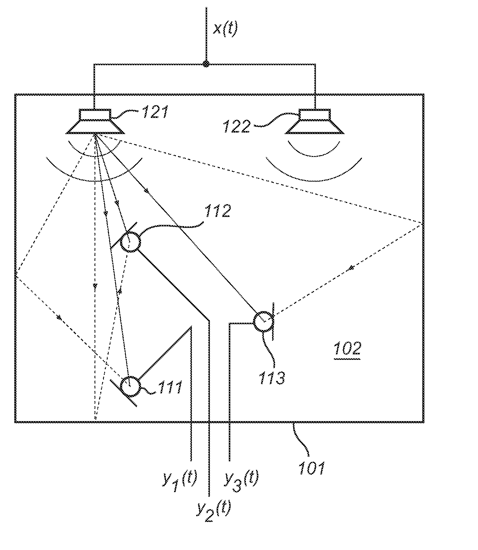
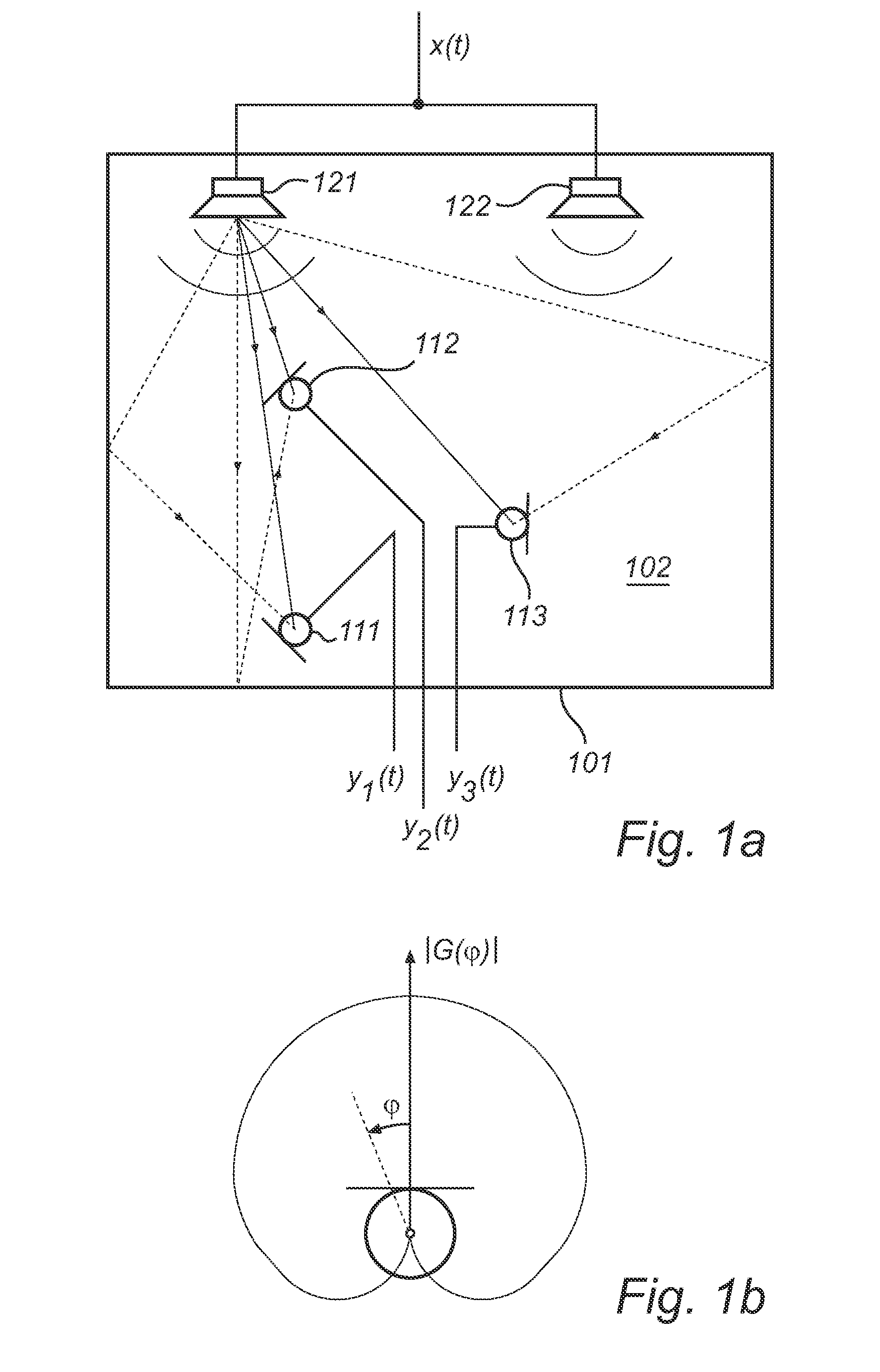
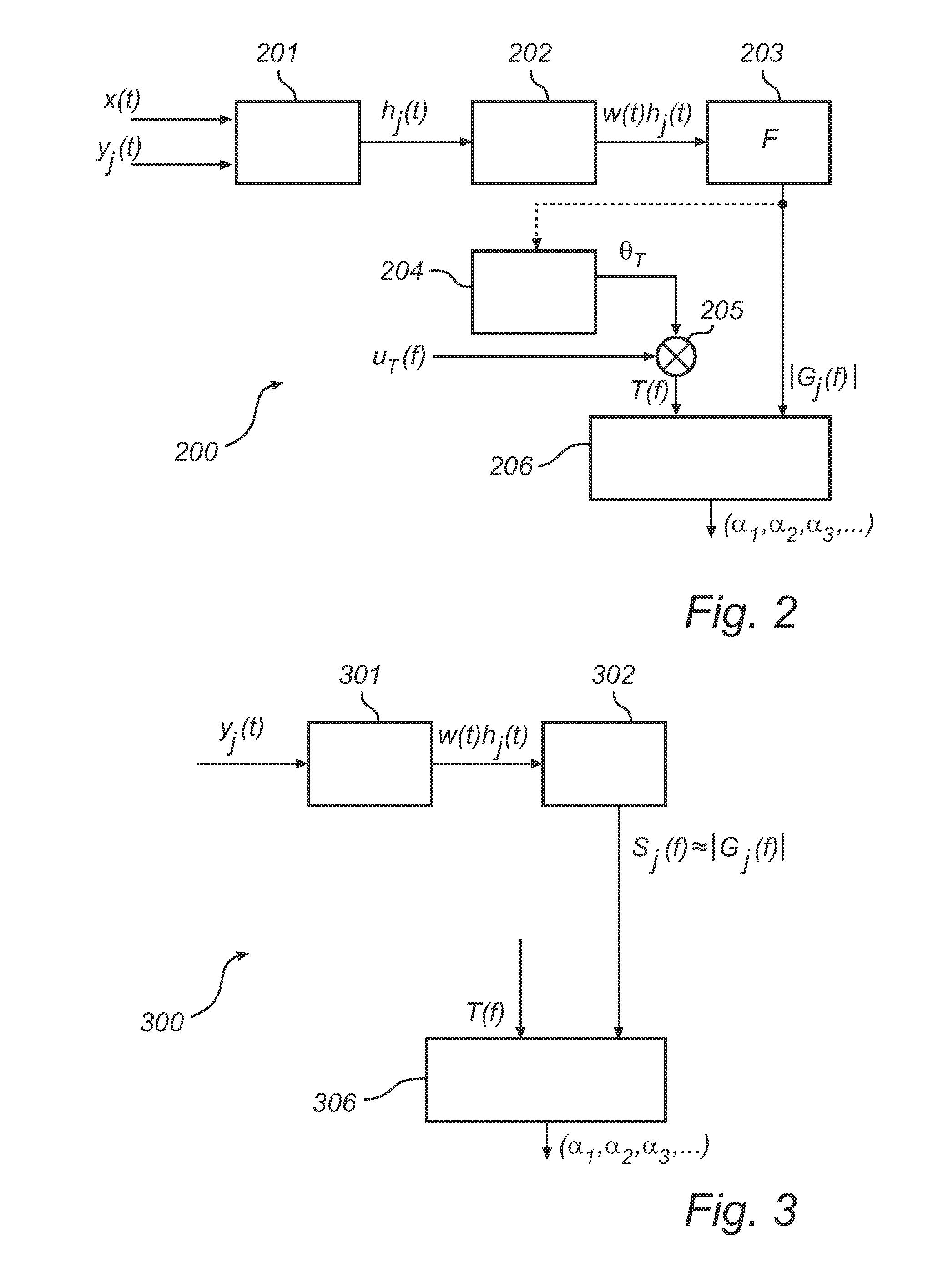
[0046]FIG. 2 is a generalized block diagram of a controller 200 according to an example embodiment, the controller 200 being adapted to interact with a plurality of acoustic sensors and at least one audio source. The sensors and source(s) may be of similar types and may be similarly arranged as the sensors 111, 112, 113 and sources 121, 122 located in the environment 102 shown in FIG. 1. A deconvolution section 201 receives at least a time-dependent output yj(t) of a sensor and deconvolves the output to provide a time-dependent impulse response ha for the sensor in respect of the audio source(s) producing the stimulus. The deconvolution may be enabled at least by one of the following options:[0047]a) The deconvolution section 201 receives, as shown in FIG. 2, a copy of the stimulus x(t) supplied to the audio sourc(e) and derives a convolution inverse x−1(t). Preferably, the copy of the stimulus is received in synchronicity with the signal actually supplied to ...


PUM


Abstract

A plurality of acoustic sensors in a non-anechoic environment are calibrated with the aim of removing manufacturing tolerances and degradation over time but preserving position-dependent differences between the sensors, The sensors are excited by an acoustic stimulus which has either time-dependent characteristics or finite duration. The calibration is to be based on diffuse-field excitation only, in which indirect propagation (including single or multiple reflections) dominate over any direct-path excitation. For this purpose, the calibration process considers only a non-initial portion of sensor outputs and / or of an impulse response derived there-from. Based on these data, a frequency-dependent magnitude response function is estimated and compared with a target response function, from which a calibration function is derived.

Description

CROSS-REFERENCE TO RELATED APPLICATIONS[0001]This application claims the benefit of priority to U.S. Provisional Patent Application Ser. No. 61 / 614,586 filed on 23 Mar. 2012, hereby incorporated by reference in its entirety.TECHNICAL FIELD OF THE INVENTION[0002]The invention disclosed herein generally relates to multi-sensor acoustic measurements and more precisely to a calibration process for a directive acoustic sensor arrangement. It is presently intended to apply the invention to voice communication systems, such as conferencing endpoints.BACKGROUND OF THE INVENTION[0003]A conferencing endpoint relies on the known response of electro-acoustic transducers (speakers and microphones) to provide an effective communication experience. However, manufacturing tolerances and degradation over time mean that response of individual transducers can vary significantly. For example, it is typical to see ±5 dB variation across the pass band of a typical electret microphone used in a conference...

Claims


Application Information

Patent Timeline
Patent Type & Authority Applications(United States)
IPC IPC(8): H04R29/00
CPCH04R29/004H04R29/006H04R2201/405H04M3/568
Inventor NEAL, TIMOTHY J.DICKINS, GLENN N.
Owner DOLBY LAB LICENSING CORP
Why Eureka
Try Eureka