
Onboard downward-looking 3D SAR sparse array antenna laying method

A sparse array and array antenna technology, applied to antennas, antenna arrays, antennas suitable for movable objects, etc., can solve the problems of complex layout design methods and limited antenna layout space, and achieve flexible installation and operation simple effect

Active Publication Date: 2014-04-30
INST OF ELECTRONICS CHINESE ACAD OF SCI
View PDF4 Cites 20 Cited by
  • Summary
  • Abstract
  • Description
  • Claims
  • Application Information

AI Technical Summary

Problems solved by technology

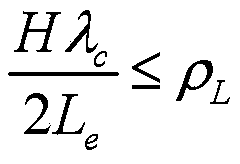
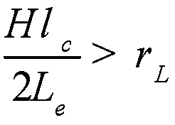
[0014] Aiming at the above-mentioned problems in the prior art, the present invention provides a sparse array antenna layout method for airborne downward-looking 3D SAR, which solves the problem of complex antenna layout design method and limited antenna layout space in airborne downward-looking 3D SAR imaging. Problems, especially the array antenna layout can be designed according to the system array resolution and observation range, and the grating lobes of the system array response function can be controlled at a reasonable level

Method used


Image

  • Onboard downward-looking 3D SAR sparse array antenna laying method
  • Onboard downward-looking 3D SAR sparse array antenna laying method
  • Onboard downward-looking 3D SAR sparse array antenna laying method

Examples


Embodiment Construction

[0029] In order to make the object, technical solution and advantages of the present invention clearer, the present invention will be described in further detail below in conjunction with specific embodiments and with reference to the accompanying drawings.

[0030] It should be noted that, in the drawings or descriptions of the specification, similar or identical parts use the same reference numerals. Implementations not shown or described in the accompanying drawings are forms known to those of ordinary skill in the art. Additionally, while illustrations of parameters including particular values ​​may be provided herein, it should be understood that the parameters need not be exactly equal to the corresponding values, but rather may approximate the corresponding values ​​within acceptable error margins or design constraints. In addition, the directional terms mentioned in the following embodiments, such as "upper", "lower", "front", "rear", "left", "right", etc., are only re...


PUM


Abstract

The invention provides an onboard downward-looking 3D SAR sparse array antenna laying method. The method aims to solve the problems that according to onboard 3D SAR system antenna laying, a platform installation space is limited and a design method is complicated; according to the flight height of an aerial carrier, an observation area maximum height change range function, a radar system work wavelength and a resolution ratio in the array direction, antenna laying design is carried out. The method is simple in operation, free of complicated computation and capable of guaranteeing that a grating lobe of a target response function in the array direction of a system is controlled to be at a reasonable level.

Description

technical field [0001] The invention relates to an airborne downward-looking 3D SAR sparse array antenna layout method. Background technique [0002] The airborne downward-looking array 3D SAR (Three-Dimensional Synthetic Aperture Radar, referred to as 3D SAR) observes the bottom area of ​​the aircraft, and realizes the resolution in the direction of wave propagation by means of pulse compression; In the array direction, the aperture synthesis is realized by arranging sparse array antennas along the wings and belly of the carrier aircraft, and then the array direction resolution is realized (see non-patent documents 1 and 2). [0003] If a large number of antenna sub-arrays are evenly arranged along the wings and belly, on the one hand, it will have a great impact on the aerodynamics of the aircraft. On the other hand, uniformly arranging a large number of array elements will also increase system cost and system complexity. Aiming at these problems, people in the field hav...

Claims


Application Information

Patent Timeline
Patent Type & Authority Applications(China)
IPC IPC(8): H01Q1/28H01Q21/00G01S13/90
Inventor 谭维贤王彦平彭学明鲍慊洪文吴一戎
Owner INST OF ELECTRONICS CHINESE ACAD OF SCI
Learn More