System and a method for improved car prognosis

a technology for prognosis and car, applied in the field of car prognosis system, can solve the problems of higher battery consumption, model does not take into account road condition, and condition effect, and achieve the effects of reducing battery consumption, reducing power life of devices, and increasing battery consumption

Active Publication Date: 2015-02-19
TATA CONSULTANCY SERVICES LTD
View PDF4 Cites 30 Cited by
  • Summary
  • Abstract
  • Description
  • Claims
  • Application Information

AI Technical Summary

Benefits of technology

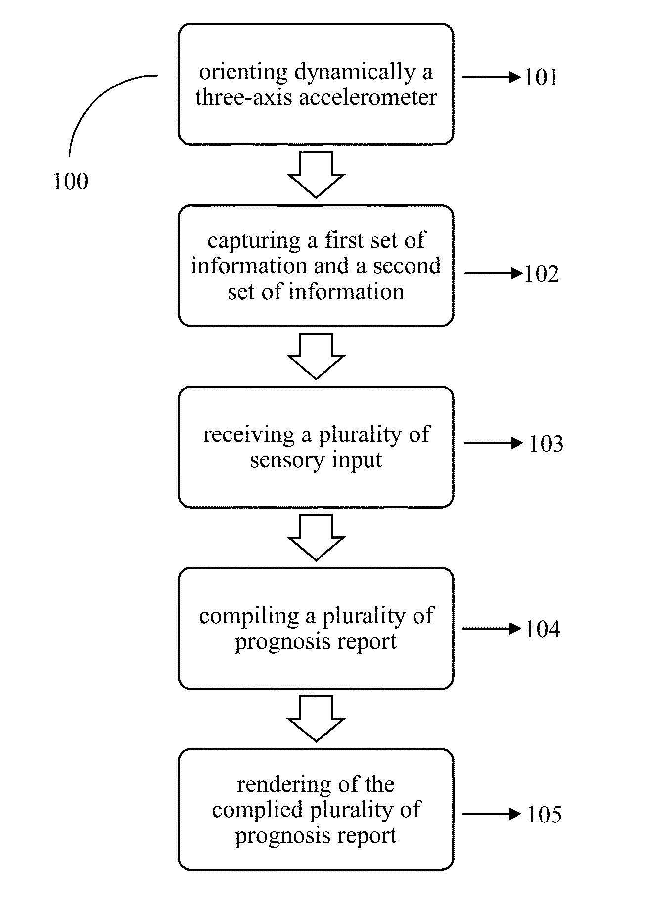
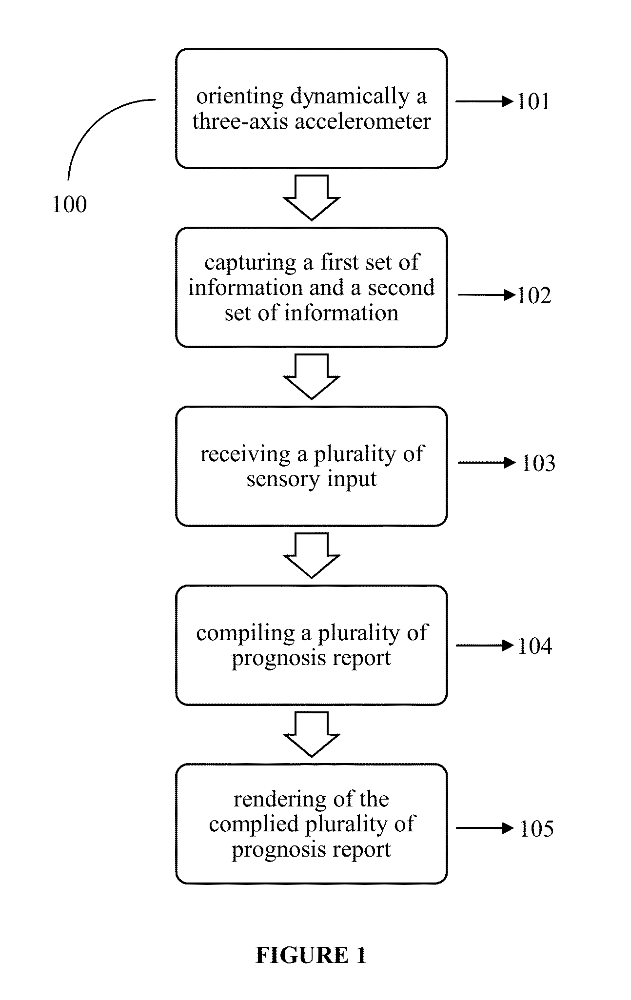
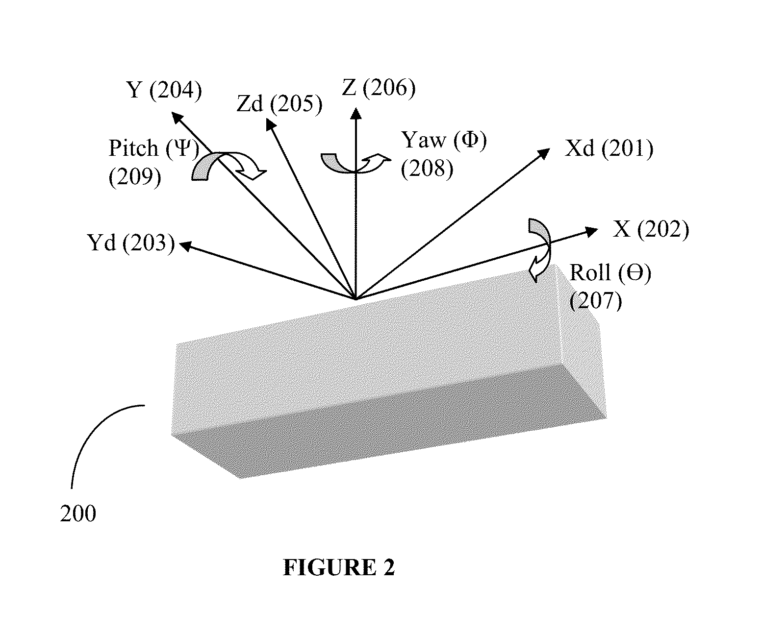
[0020]The 3-axis accelerometer available in the smart phones or personal communication devices or electronic tablets currently used to monitor the road conditions, are either fixed or docked in a known orientation. At present, the orientation correction to capture data is done using supporting devices such as magnetometer, gyroscope, GPS along with the velocity of the vehicle. In addition, the current techniques use a sampling rate or sampling frequency of 25 Hertz (Hz) to 500 Hertz (Hz) with 256 to 1000 points to detect bump or potholes. The use of higher frequency produces larger sets of data requiring higher CPU cycles to process, which in effect requires higher battery consumption thereby reducing the power life of the devices. Therefore, in another aspect a method is provided that dynamically orients the 3-axis accelerometer without the use of any external devices such as magnetometer, gyroscope, or GPS. The 3-axis accelerometer according to said method can orients itself automatically before capturing data relating to road condition and driving behavior.
[0021]In another aspect of the present invention the 3-axis accelerometer utilizes a lower sampling rate/frequency about 4 Hertz (Hz) ...

Problems solved by technology

These existing models do not take into account the road condition on which it is being driven or the way a driver maneuvers the vehicle.
However, these parameters have a major effect on the condition of ...

Method used


Image

  • System and a method for improved car prognosis
  • System and a method for improved car prognosis
  • System and a method for improved car prognosis

Examples


Embodiment Construction

[0028]Some embodiments of this invention, illustrating its features, will now be discussed:

[0029]The words “comprising,”“having,”“containing,” and “including,” and other forms thereof, are intended to be equivalent in meaning and be open ended in that an item or items following any one of these words is not meant to be an exhaustive listing of such item or items, or meant to be limited to only the listed item or items.

[0030]It must also be noted that as used herein and in the appended claims, the singular forms “a,”“an,” and “the” include plural references unless the context clearly dictates otherwise. Although any systems, methods, apparatuses, and devices similar or equivalent to those described herein can be used in the practice or testing of embodiments of the present invention, the preferred, systems and parts are now described.

[0031]The disclosed embodiments are merely exemplary of the invention, which may be embodied in various forms.

DEFINITIONS OF THE TERMS

[0032]The term veh...


PUM


Abstract

A system and method for a real-time prognosis of a vehicle comprising a personal communication device comprising an arbitrarily oriented three-axis accelerometer configured to capture a pitch motion and/or roll motion of the vehicle and an onboard diagnostics system communicably connected with the personal communication device enabling bi-directional communication. The personal communication device comprising a processor configured for geometric mapping of a three dimensional Cartesian coordinate of the three-axis accelerometer with the vehicle. The processor virtually orients the coordinates of three-axis accelerometer to coincide with the coordinates of the vehicle. The arbitrarily oriented three-axis accelerometer is configured to capture a road condition and a driver behaviour using a sampling rate between 4 Hertz (Hz) to 10 Hertz (Hz). The system for the real-time prognosis of the vehicle, wherein the real-time prognosis utilizes at least one predictive analysis model to determine real-time prognosis for the said vehicle.

Description

FIELD OF THE INVENTION[0001]The present invention relates to car prognosis system, more particularly the present invention relates to a system, a method, and an apparatus for real-time car prognosis using road condition, driver behaviour, and onboard diagnostics.BACKGROUND OF THE INVENTION[0002]Earlier, preventive maintenance for a vehicle largely relied on a visual inspection of the vehicle and its systems by a driver or an auto-mechanic, which invariably depended upon their experience. With development of electronic processors, vehicle diagnostic systems like onboard diagnostic system (OBD) for vehicle began to be widely used for fault-detection and scheduling vehicle maintenance. Currently the OBD systems are standard equipment on all the modern vehicles. The interfaces for current OBD system are governed by standards like SAE J1580 PWM / VPW, or ISO 15765 CAN, or SAE J2284-3. The information relating to the vehicle captured by the OBD play an important role in understanding factor...

Claims


Application Information

Patent Timeline
IPC IPC(8): G07C5/00G01P15/18
CPCG01P15/18G07C5/008B60W2520/14B60W2520/16B60W2520/18G07C5/0808B60W50/14B60W40/06B60W2420/905B60W2552/00B60W2556/45
Inventor PAL, ARPANBHAUMIK, CHIRABRATAGHOSH, KALLOLBISWAS, PROVATSINHA, ANIRUDDHACHATTOPADHYAY, TANUSHYAMSINHARAY, ARIJITSYED, MOHD BILAL ARIF
Owner TATA CONSULTANCY SERVICES LTD
Why Eureka
Try Eureka