
Method for determining a state of credibility of measurements of an incidence sensor of an aircraft and corresponding system

a technology of an incidence sensor and a state of credibility, which is applied in the direction of aircraft component testing, measurement devices, instruments, etc., can solve the problems of meteorological or mechanical factors, incorrect measurement readings, and performing inappropriate maneuvers

Active Publication Date: 2015-02-26
DASSAULT AVIATION
View PDF7 Cites 11 Cited by
  • Summary
  • Abstract
  • Description
  • Claims
  • Application Information

AI Technical Summary

Benefits of technology

The invention aims to detect any malfunctions in the aircraft's sensors and alert the pilot about them. This way, the pilot will have reliable alternative data and information when flying the aircraft.

Problems solved by technology

They are thus exposed to meteorological or mechanical factors which can affect or alter the operation thereof, in particular by clogging the orifices of these probes with frost or dust or insects, or by blocking the vane devices.
Such failures lead to the generation of incorrect measurement readings, and in particular the display of false incidences, speeds and / or altitudes that may lead to the pilot performing inappropriate maneuvers.
For example, false flight control information can lead to the stalling of the aircraft or loss of control thereof on account of excessive speed.
However, this solution has not proven to be entirely satisfactory.
Indeed, the existing stand by sensor probes are for the most part of the protruding type and as a consequence present the same risks of malfunction or failure as the probes that they are intended to eventually replace.
Thus, in the event of the malfunction or failure of measurement probes, no reliable measurements are provided to the pilot.
Moreover, the pilot does not have any available means for verifying the reliability of the data and information provided by the sensor probes.

Method used


Image

  • Method for determining a state of credibility of measurements of an incidence sensor of an aircraft and corresponding system
  • Method for determining a state of credibility of measurements of an incidence sensor of an aircraft and corresponding system
  • Method for determining a state of credibility of measurements of an incidence sensor of an aircraft and corresponding system

Examples


Embodiment Construction

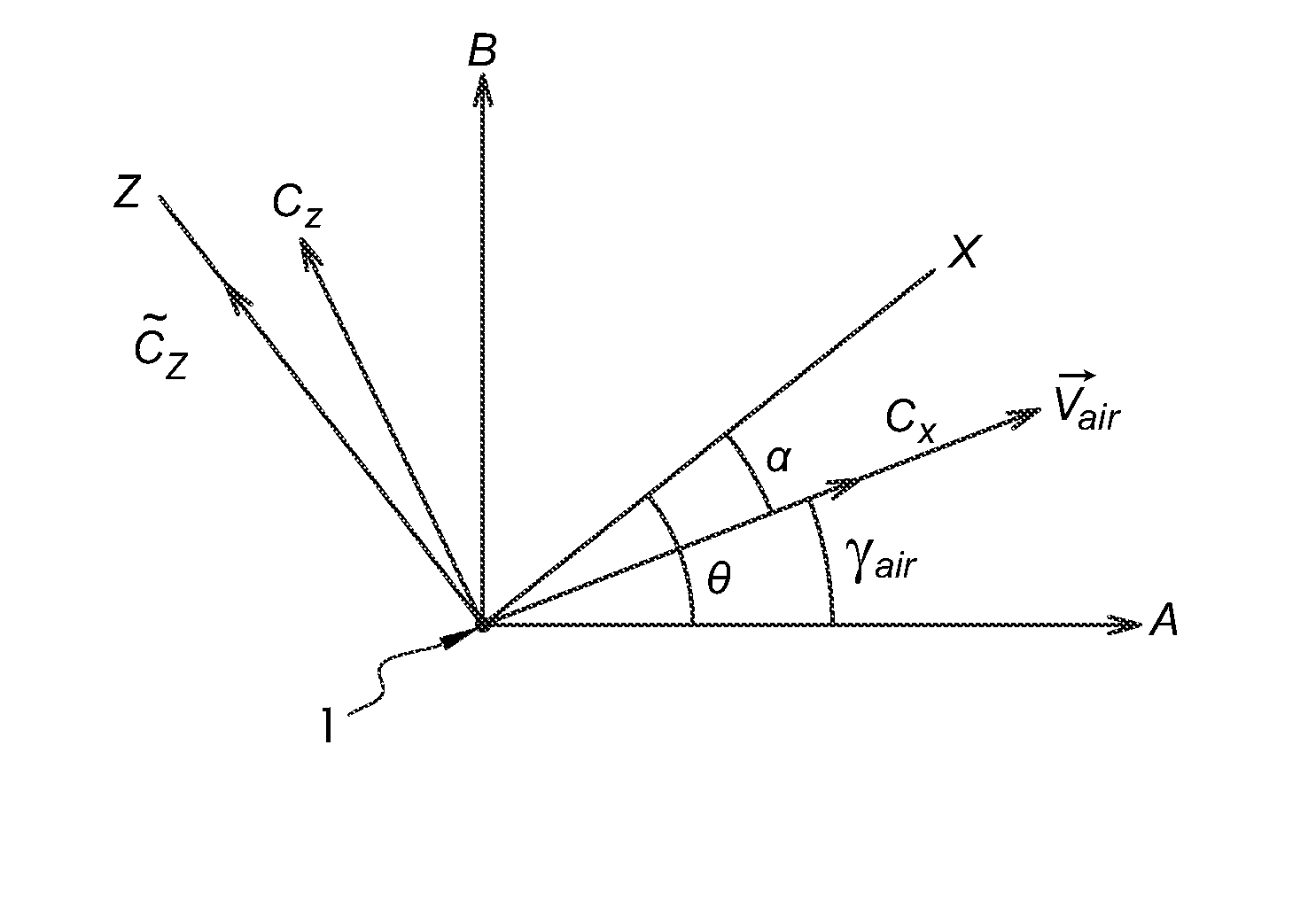
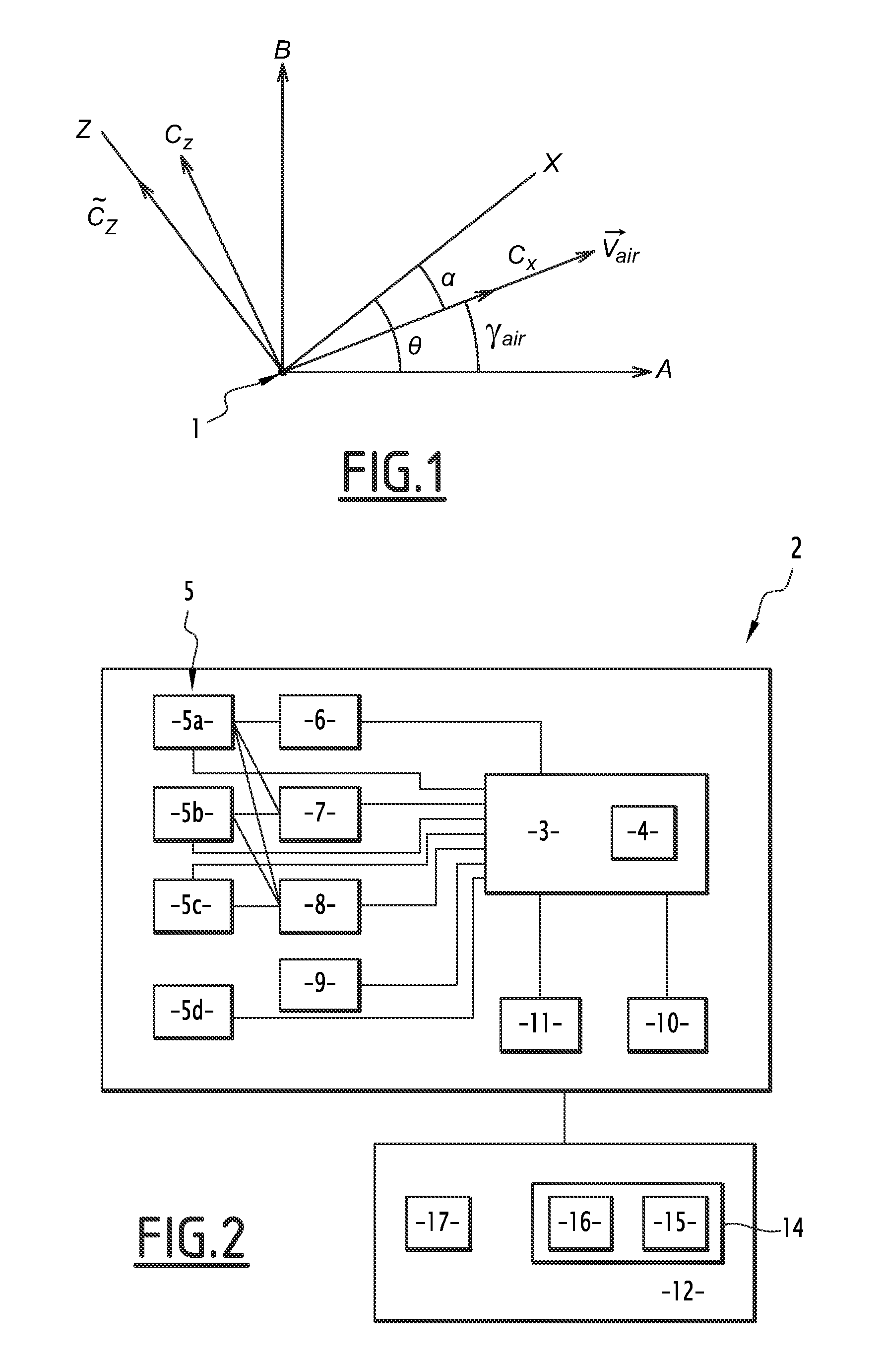
[0045]FIG. 1 represents, in a schematic manner, an aircraft 1 in flight to which is applied the method according to the invention.

[0046]The aircraft 1 is represented in FIG. 1 by its sole centre of gravity. Its longitudinal axis is oriented along an axis X, which forms with the horizontal A an angle θ known as the aircraft pitch angle. It moves relative to the air along a velocity vector {right arrow over (Vair)}, that forms with the horizontal A an angle γair known as the flight path angle of the aircraft. The angle α between the longitudinal axis X of the aircraft 1 and its velocity vector is known as the angle of incidence. These angles thus satisfy the relationship: θ=α+γair.

[0047]The true air speed {right arrow over (VP)} of the aircraft, which is its speed relative to the air in a horizontal plane, is linked to its speed {right arrow over (VS)} relative to the ground in this horizontal plane by the velocity triangle in accordance with the relationship: {right arrow over (VP)}=...


PUM


Abstract

A method for determining a state of credibility of measurements of an incidence sensor of an aircraft is provided. This method includes at least one coherence test between incidence measurements from said incidence sensor, and the measurements of a flight characteristic of the aircraft, distinct from the incidence. The coherence test includes determining an incidence value from said incidence sensor, determining said flight characteristic of the aircraft, determining a value of at least one indicator of the coherence of the incidence value with the value of said flight characteristic, and activating a low state of credibility, in which the measurements of said incidence sensor are deemed unreliable, or an intermediate state of credibility, in which the measurements from said incidence sensor are deemed coherent with said flight characteristic, based on the value of said coherence indicator.

Description

[0001]The present invention relates to a method for determining a state of credibility of measurements done by at least one incidence sensor of an aircraft during a flight of said aircraft. The flight operation and control of an aircraft is dependent on the knowledge of the flight parameters of the latter, such as its speed relative to the ambient air, its altitude and incidence.BACKGROUND[0002]These parameters are determined by means of sensor probes located on the fuselage of the aircraft. In a known manner, these sensor probes include static pressure sensors, Pitot probes for measuring the total pressure, incidence probes mounted on a pneumatic device or a vane / paddle type device, and total temperature probes.[0003]These probes are then connected to the means for determining the corresponding magnitude or quantity. In particular, an anemometer determines the speed of the aircraft relative to the air based on the measurements of total and static pressure, and an altimeter determin...

Claims


Application Information

Patent Timeline
IPC IPC(8): G01P13/02
CPCG01P13/025B64F5/60G01P21/025
Inventor DUPONT DE DINECHIN, SEBASTIEN
Owner DASSAULT AVIATION
Learn More