Electronic disc brake

a technology of electronic disc brakes and brake discs, applied in the direction of brake elements, slack adjusters, braking members, etc., can solve the problems of friction pad wear, high drag, high drag, etc., and achieve the effect of preventing drag, ensuring normal braking force, and reducing nois

Active Publication Date: 2015-02-26
HL MANDO CORP
View PDF7 Cites 12 Cited by
  • Summary
  • Abstract
  • Description
  • Claims
  • Application Information

AI Technical Summary

Benefits of technology

[0014]It is an aspect of the present invention to provide an electronic disc brake which is equipped with a low-pressure spring and a high-pressure spring to operate according to low pressure and high pressure when braking is performed, so as to prevent a drag phenomenon by enhancing the effect of return of a piston and to secure a gap between a disc and friction pads by forming a gap between the low-pressure spring and the high-pressure spring in the longitudinal direction.
[0015]It is another aspect of the present invention to provide an electronic disc brake which is equipped with an adjustor so as to improve brake feeling by preventing pad plates from moving away from a disc and maintaining a constant gap between the pad plates and the disc.
[0022]As is apparent from the above description, the electronic disc brake according to the embodiments of the present invention is provided with the low-pressure spring configured to operate according to low pressure and the high-pressure spring configured to operate according to high pressure in braking operation, and thus may not only prevent drag by moving the piston backward, but also secure a gap between the disc and the friction pads by forming a gap between the low-pressure spring and the high-pressure spring in the longitudinal direction. Accordingly, wear of the friction pads due to unnecessary friction between the friction pads and the disc and noise resulting therefrom may be prevented, and normal braking force may be ensured.
[0023]Moreover, initial brake feeling may be improved through elimination of increase in the amount of roll-back according to wear of the friction pads which are pressed against the disc.

Problems solved by technology

If the return distance of the piston 22 is short, the friction pads 12 attached to the pad plates 11 may not be sufficiently separated from the disc D when the braking operation is terminated, resulting in wear of the friction pads 12.
That is, the amount of roll-back given according to the machining allowance of the cylinder 21 and friction between the sealing member 30 and the piston 22 may result in high drag.
Thereby, the return distance of the piston 22 may be short, resulting in high drag.
Meanwhile, in the case of using a compression spring (not shown), the amount of roll-back may increase as the friction pad 12 wears, resulting in poor initial brake feeling.
Further, excessive roll-back of the piston 22 may occur due to the compression spring, resulting in a sinking brake pedal.

Method used


Image

  • Electronic disc brake
  • Electronic disc brake
  • Electronic disc brake

Examples


Embodiment Construction

[0031]Reference will now be made in detail to the preferred embodiments of the present invention, examples of which are illustrated in the accompanying drawings. It should be understood that the terms used in the specification and appended claims should not be construed as limited to general and dictionary meanings but be construed based on the meanings and concepts according to the spirit of the present invention on the basis of the principle that the inventor is permitted to define appropriate terms for the best explanation. The preferred embodiments described in the specification and shown in the drawings are illustrative only and are not intended to represent all aspects of the invention, such that various equivalents and modifications can be made without departing from the spirit of the invention.

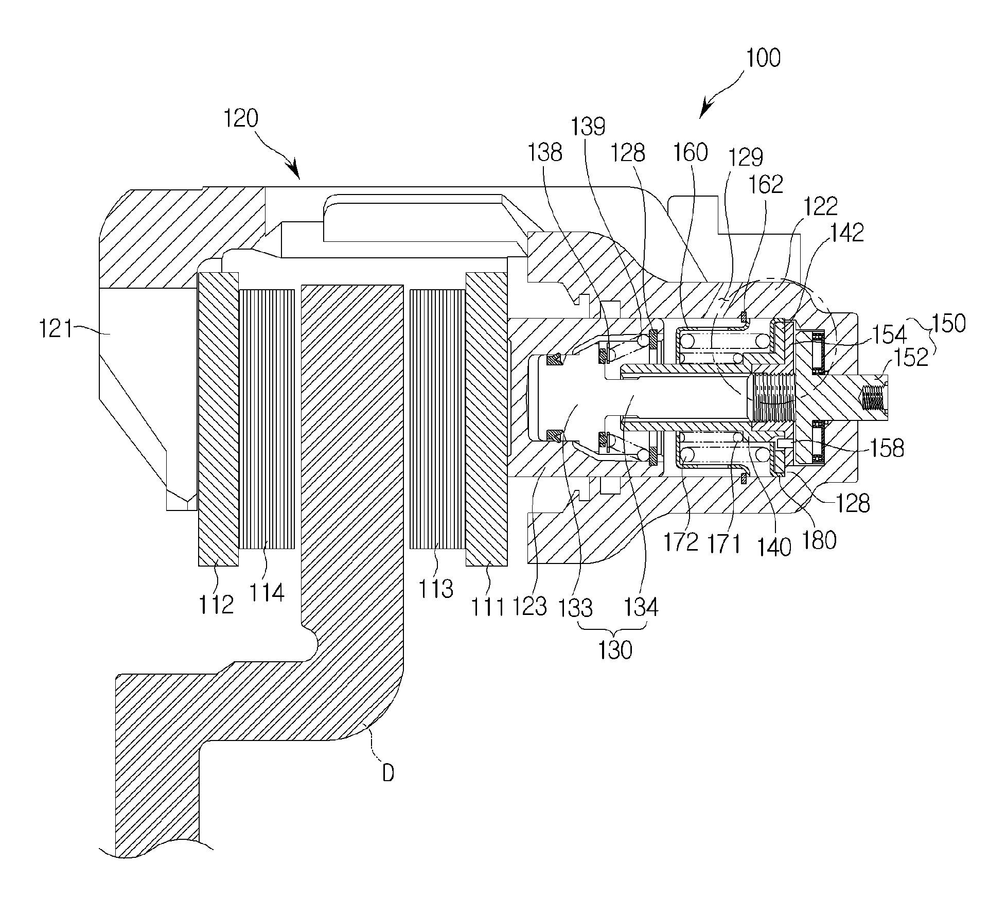
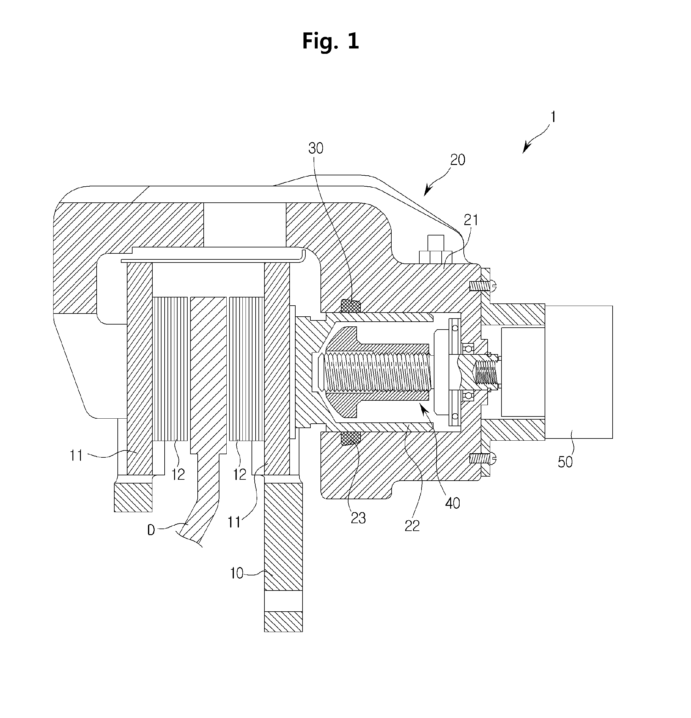
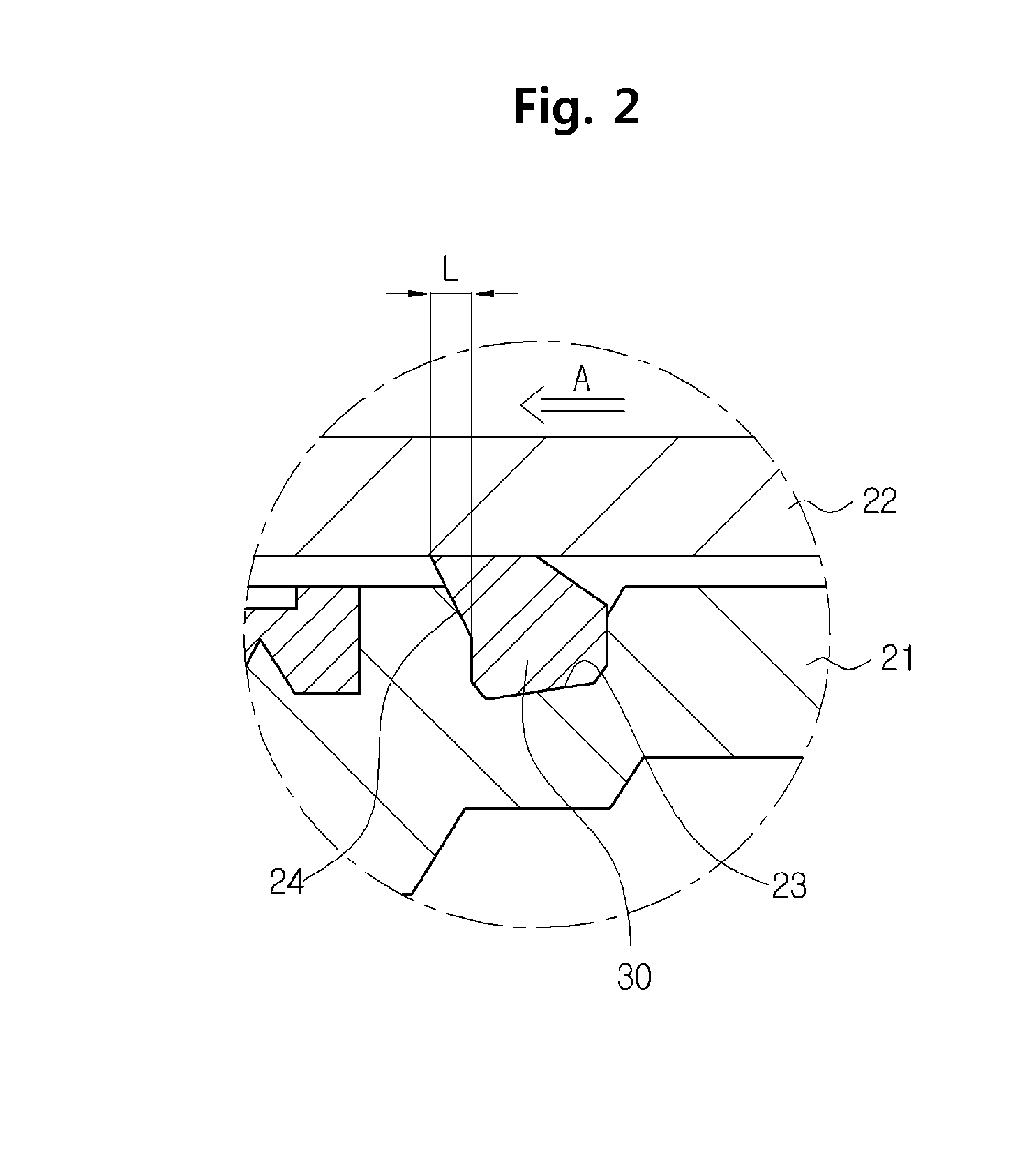
[0032]FIG. 3 is a cross-sectional view illustrating an electronic disc brake according to an exemplary embodiment of the present invention, and FIG. 4 is an exploded perspective view i...


PUM


Abstract

Disclosed is an electronic disc brake. The electronic disc brake includes a caliper housing at which a piston is installed, a carrier coupled with the caliper housing, a pair of pad plates installed at the carrier to be slidable toward a disc, an adjuster to prevent the pad plates from moving away from the disc and maintain the pad plates at a certain distance from the disc, a push rod screw-coupled to the adjuster, a spindle unit coupled to the push rod and installed at a cylinder of the caliper housing, a spring case forming an accommodation space between the cylinder and the push rod, a low-pressure spring and a high-pressure spring arranged in parallel in the spring case, and a support plate slidably installed in the cylinder so that a gap is formed between the low-pressure spring and the high-pressure spring in the longitudinal direction.

Description

CROSS-REFERENCE TO RELATED APPLICATION[0001]This application claims the benefit of Korean Patent Application No. 2013-0100788, filed on Aug. 26, 2013 in the Korean Intellectual Property Office, the disclosure of which is incorporated herein by reference.BACKGROUND[0002]1. Field[0003]Embodiments of the present invention relate to an electronic disc brake, and more particularly to, a disc brake which may stably return a piston when braking operation is terminated and improve the effect of return of the piston.[0004]2. Description of the Related Art[0005]In general, a disc brake is a device that is used to slow or stop a vehicle by forcibly pressing friction pads against both sides of a disc rotating together with a wheel of the vehicle to stop rotation of the disc. Recently, an electronic parking brake system configured to electronically control operation of a parking brake is installed to a disc brake to perform a parking brake function.[0006]To reduce brake drag that is caused by co...

Claims


Application Information

Patent Timeline
Patent Type & Authority Applications(United States)
IPC IPC(8): F16D65/38F16D65/58
CPCF16D65/58F16D65/38F16D65/567F16D65/60F16D65/00F16D65/09F16D65/097
Inventor LEE, JAE-HYUNKONG, YOUNG-HUN
Owner HL MANDO CORP
Why Eureka
Try Eureka