Multi-functional measuring and waveform-generating equipment with probe

a multi-functional, waveform-generating technology, applied in the direction of digital variable/waveform display, electric pulse generator details, instruments, etc., can solve the problems of low portability, occupying a large space when being used, conventional measurement apparatus as above, etc., to achieve convenient portability and easy manipulation

Active Publication Date: 2015-02-26
INJE UNIV IND ACADEMIC COOP FOUND
View PDF2 Cites 6 Cited by
  • Summary
  • Abstract
  • Description
  • Claims
  • Application Information

AI Technical Summary

Benefits of technology

The present invention aims to solve the problems of conventional equipment by providing a multi-functional measuring and waveform-generating tool with a probe. This tool can measure various electrical quantities and generate signals with different waveforms using a single device. This makes it easy to manipulate, convenient to carry, and has multiple functions.

Problems solved by technology

The patent text discusses the classification of measuring equipment based on the types of quantities being measured. However, the conventional art has limitations such as being bulky and heavy, and not being able to measure several functions simultaneously. The technical problem addressed in this patent is to provide a more portable and versatile measuring apparatus that can measure various quantities accurately and easily.

Method used


Image

  • Multi-functional measuring and waveform-generating equipment with probe
  • Multi-functional measuring and waveform-generating equipment with probe
  • Multi-functional measuring and waveform-generating equipment with probe

Examples


Embodiment Construction

[0041]The following detailed description is provided to assist the reader in gaining a comprehensive understanding of the methods, apparatuses, and / or systems described herein. Accordingly, various changes, modifications, and equivalents of the systems, apparatuses and / or methods described herein will be suggested to those of ordinary skill in the art. Also, descriptions of well-known functions and constructions may be omitted for increased clarity and conciseness.

[0042]Hereinafter, exemplary embodiments of the present disclosure will be described in detail by referring to the attached Drawings.

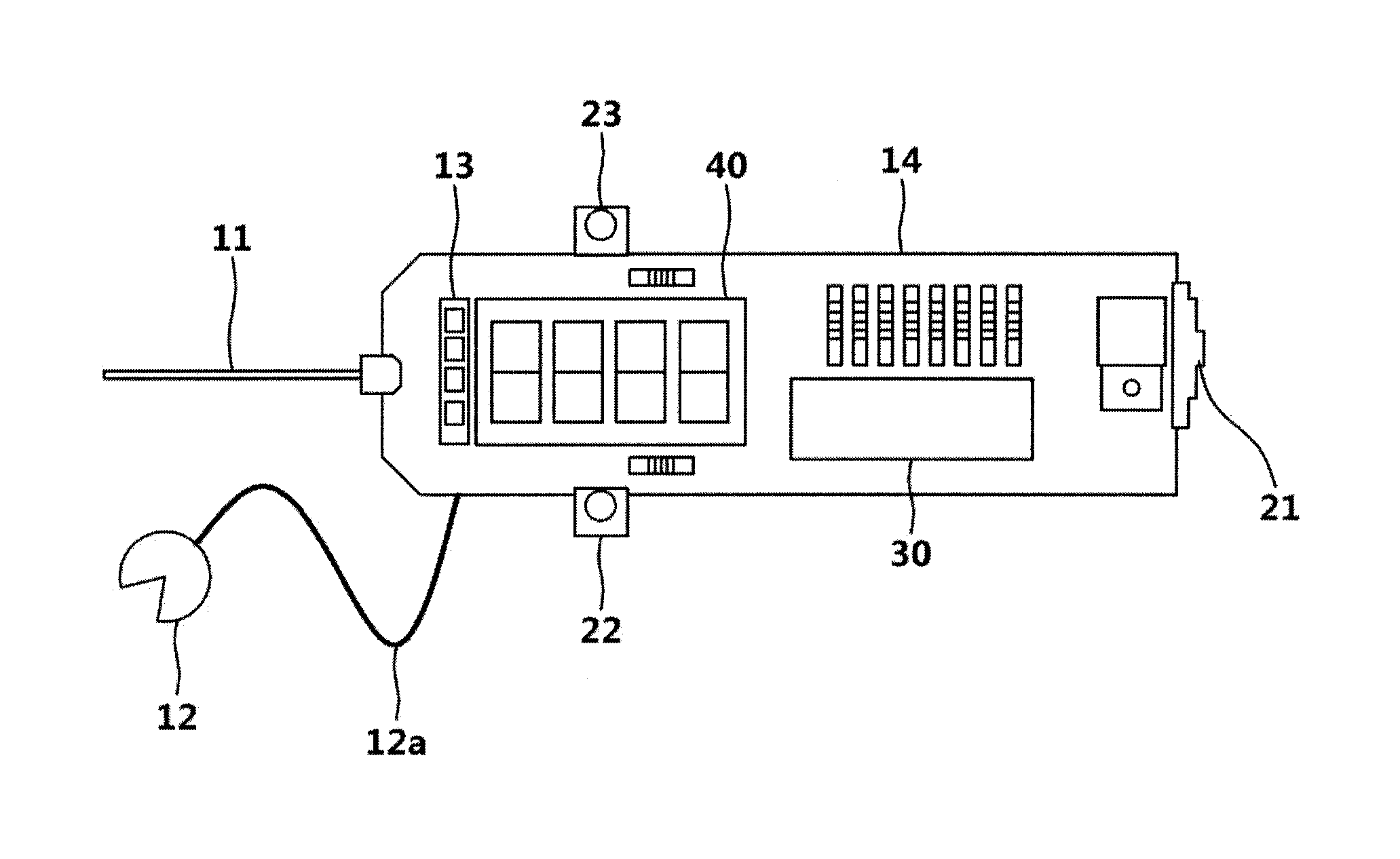
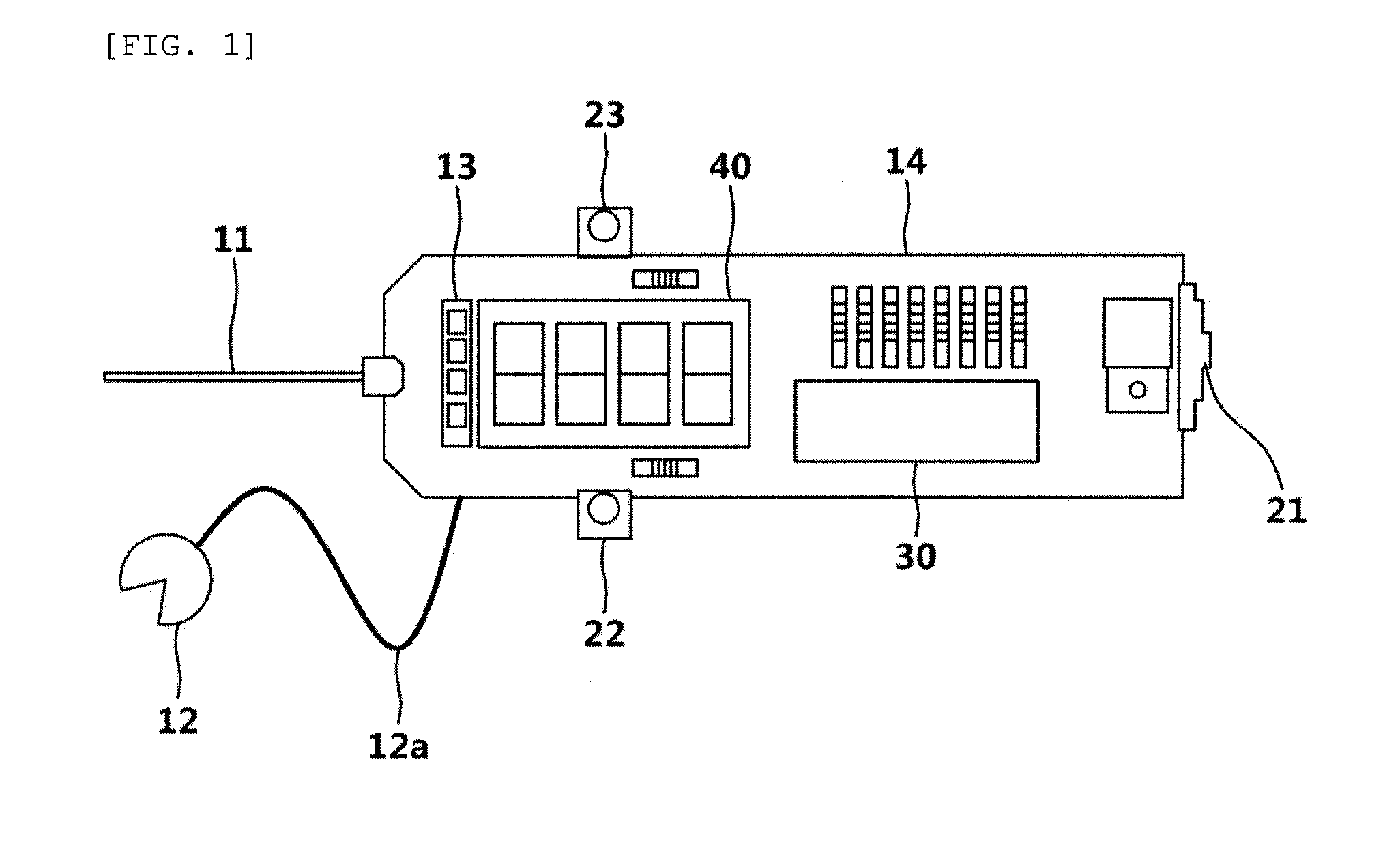
[0043]FIG. 1 illustrates a plan view of a Multi-functional measuring and waveform-generating equipment with a probe according to an exemplary embodiment of the present disclosure;

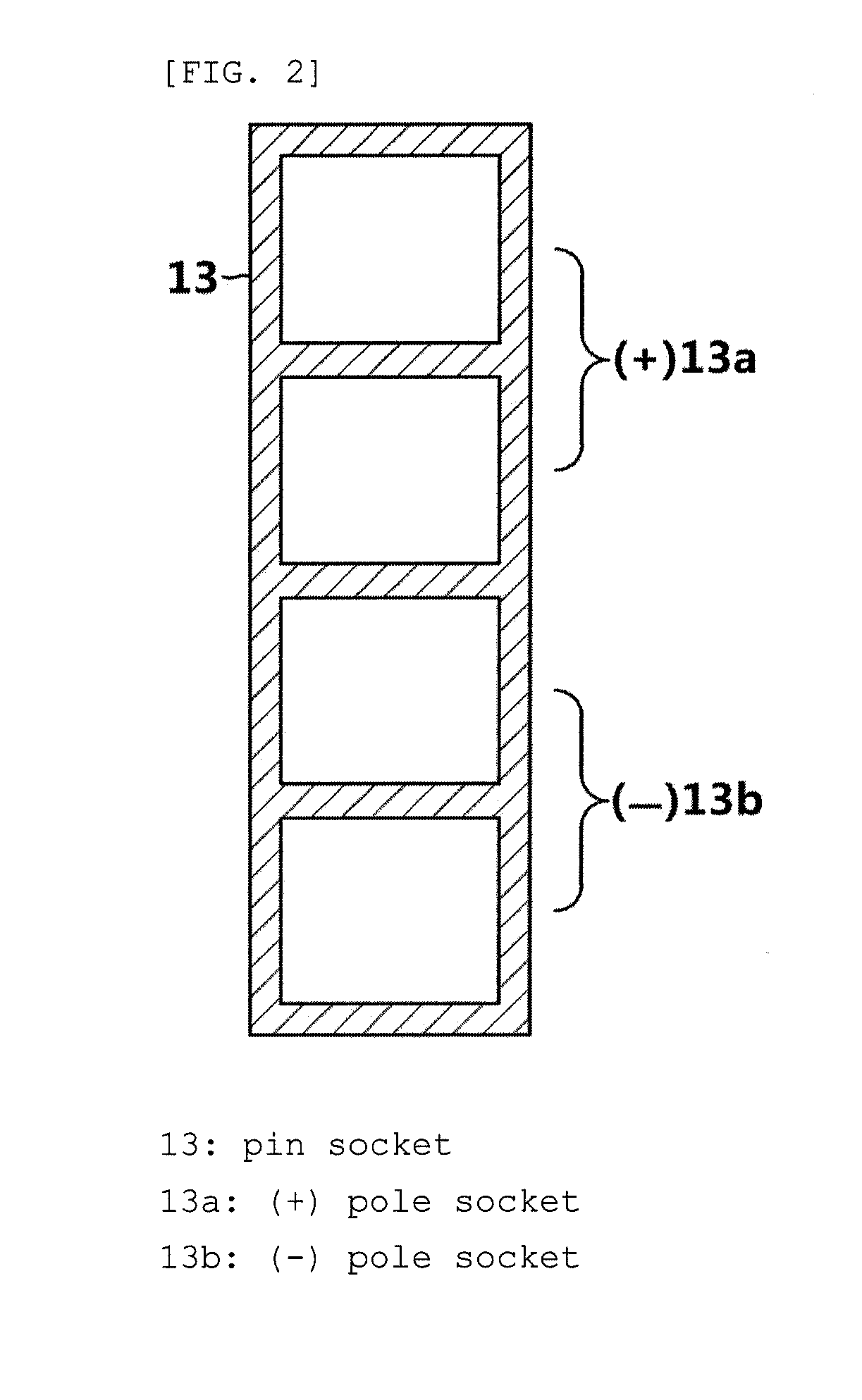
[0044]FIG. 2 illustrates a detailed view of a pin socket illustrated in FIG. 1; and

[0045]FIG. 3 illustrates a block view of the Multi-functional measuring and waveform-generating equipment with a probe illustrated in...


PUM


Abstract

There is provided a Multi-functional measuring and waveform-generating equipment with a probe. The equipment is capable of measuring element values of electric or electronic devices and electrical quantities such as a voltage, and generating electrical signals with various waveforms. Also, a user can conveniently manipulate and handily carry it. The equipment provides functions of measuring a voltage, a resistance, an inductance, capacitance, a frequency, the number of pulses, and the voltage level of a logic signal; verifying diode polarities, measuring the voltage level of a pulse signal, and modes generating a rectangular pulse train and a PWM signal by the simple combinations of two switches. Additionally, it also offers a much cheaper equipment than other existing expensive apparatuses, and provide better usability at experimental environments because it is small-sized, light, and conveniently portable, compared to conventional equipments that are large-sized, heavy, and not easy to carry.

Description


Claims


Application Information

Patent Timeline
Owner INJE UNIV IND ACADEMIC COOP FOUND
Why Eureka
Try Eureka