Display device, electronic device comprising same, and drive method for display device

a technology of electronic devices and display devices, applied in the field of display devices, can solve the problems of low backlight power consumption, achieve the effects of reducing power consumption, reducing power consumption, and suppressing the reduction of display quality

Active Publication Date: 2015-02-26
SHARP KK
View PDF1 Cites 15 Cited by
  • Summary
  • Abstract
  • Description
  • Claims
  • Application Information

AI Technical Summary

Benefits of technology

[0041]In the first aspect of the present invention, the duration of the first period is less than or equal to the second period during the transition period in which the intensity of the light source gradually changes in accordance with gradual changes of the images to be displayed from a first image to a second image. Accordingly, the screen is always refreshed in each phase of the change in intensity of the light source. As a result, during the transition period, the image displayed on the screen corresponds to the intensity of the light source that should originally correspond to that image. Therefore, during the transition period, the image displayed on the screen has its original brightness. Thus, for example, even in the case where pause drive with the refresh period followed by the no-refresh period is performed, as in the case where normal drive with only the refresh period is performed, it is possible to sufficiently suppress reduction in display quality due to the use of the function of changing the intensity of the light source in accordance with the image to be displayed on the screen (e.g., the CABC function).
[0042]The second aspect of the present invention renders it possible to achieve similar effects to those achieved by the first aspect of the present invention, even in modes for which the intensity control portion is provided in the control portion.
[0043]In the third or tenth aspect of the present invention, the screen is always refreshed in each phase of the

Problems solved by technology

For example, in the case where a dark image is displayed, with the CABC function, which correlates the image to be displayed

Method used


Image

  • Display device, electronic device comprising same, and drive method for display device
  • Display device, electronic device comprising same, and drive method for display device
  • Display device, electronic device comprising same, and drive method for display device

Examples


first embodiment

1. First Embodiment

[0068]

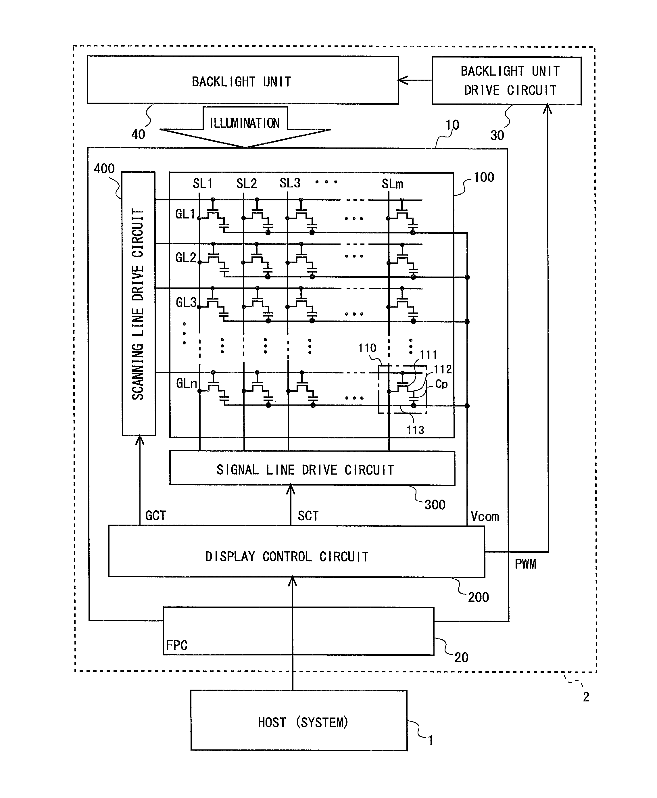
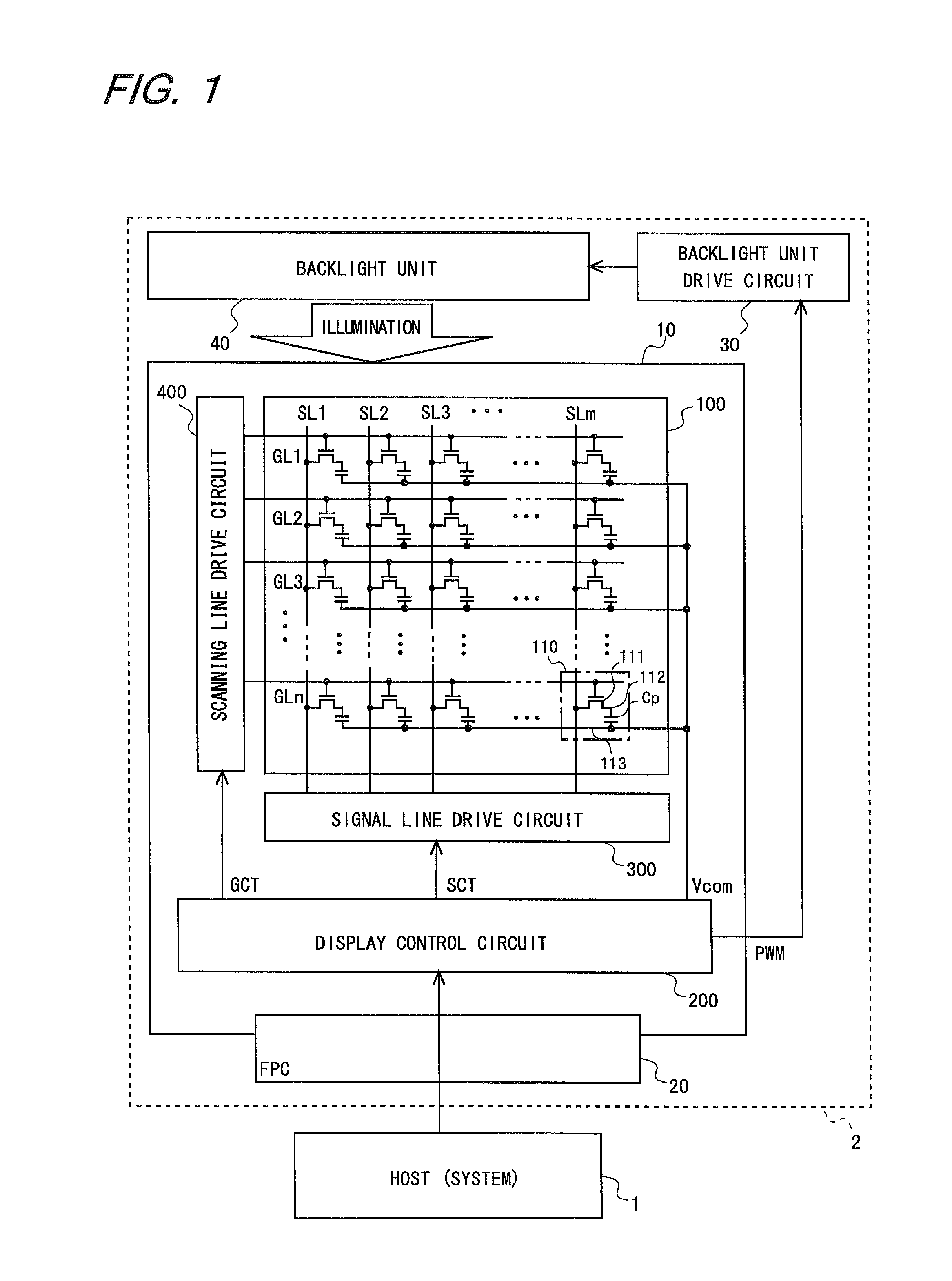
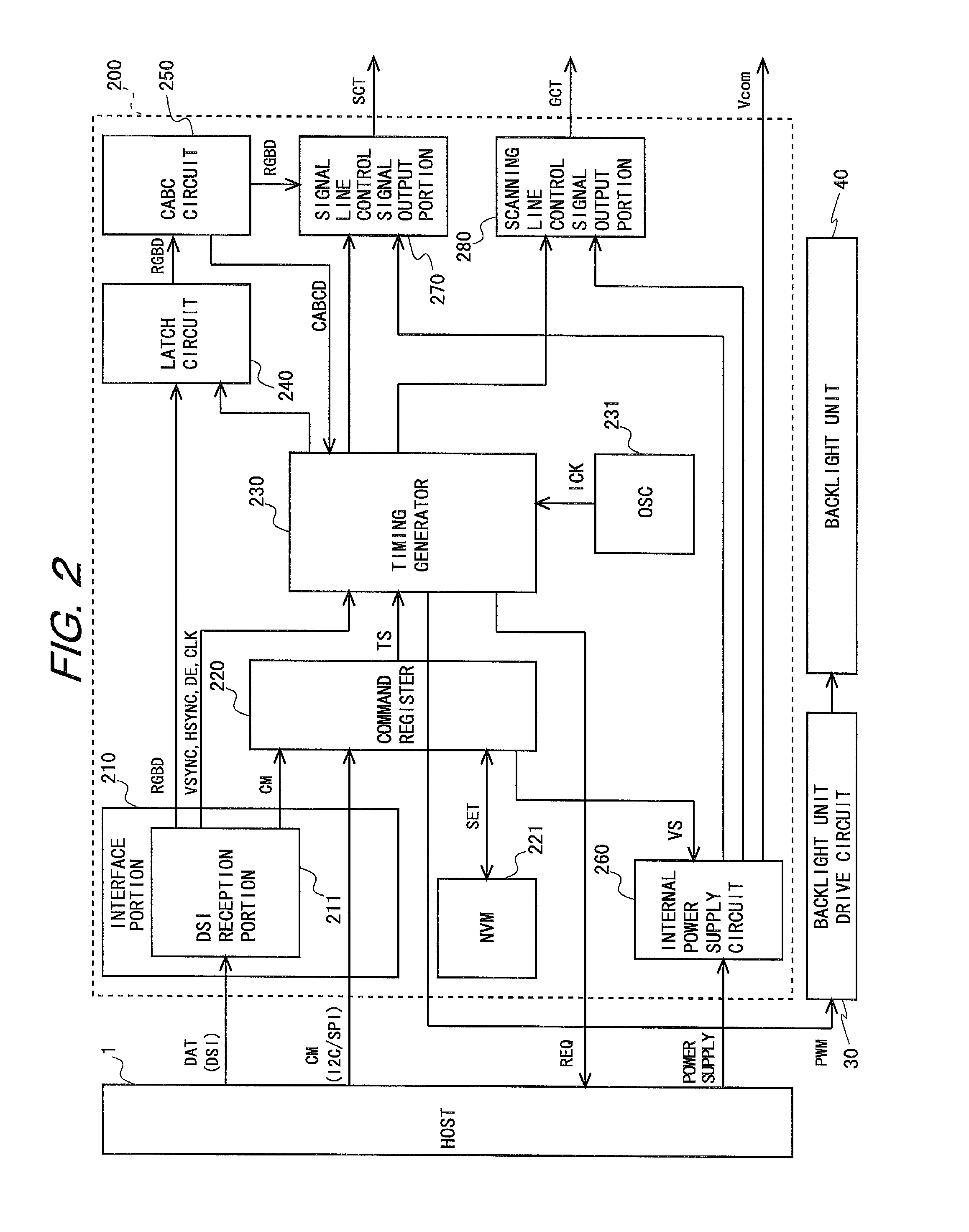
[0069]FIG. 1 is a block diagram illustrating the configuration of an electronic device according to the first embodiment of the present invention. This electronic device consists of a host (system) 1 and a liquid crystal display device 2. The host 1 has a CPU as a main component. The liquid crystal display device 2 includes a liquid crystal display panel 10, a backlight unit drive circuit 30, which acts as a light source drive portion, and a backlight unit 40. The liquid crystal display panel 10 is transmissive or semi-transmissive. The liquid crystal display panel 10 is provided with an FPC (Flexible Printed Circuit) 20 for external connection. In addition, a display portion 100, a display control circuit 200, which acts as a control portion, a signal line drive circuit 300, and a scanning line drive circuit 400 are provided on a substrate of the liquid crystal display panel 10. Note that both or one of the signal line drive circuit 300 and the scanning lin...

second embodiment

2. Second Embodiment

[0112]

[0113]FIG. 6 is a diagram describing an operational example of a liquid crystal display device 2 in a second embodiment of the present invention. Note that the present embodiment is basically the same as the first embodiment except for operations, and therefore, any descriptions of their common points will be omitted. In the present embodiment, as in the first embodiment, the duration of the sub-transition period is five frames, and 7.5-Hz pause drive is performed in the period when image X is displayed on the screen prior to the transition period. That is, the duration of the vertical display period is eight frames. In the first embodiment, once the transition period starts, 7.5-Hz pause drive switches to 60-Hz normal drive, so that the duration of the vertical display period changes from eight frames to one frame.

[0114]However, in the present embodiment, once the transition period starts, 7.5-Hz pause drive switches to 12-Hz pause drive. Accordingly, the ...

third embodiment

3. Third Embodiment

[0118]

[0119]FIG. 7 is a diagram describing an operational example of a liquid crystal display device 2 in a third embodiment of the present invention. Note that the present embodiment is basically the same as the first embodiment except for operations, and therefore, any descriptions of their common points will be omitted. In the present embodiment, in the present embodiment, as in the first embodiment, the duration of the sub-transition period is five frames, and 7.5-Hz pause drive is performed in the period where image X is displayed on the screen prior to the transition period, as in the first embodiment. That is, the duration of the vertical display period is eight frames. In the first embodiment, once the transition period starts, 7.5-Hz pause drive switches to 60-Hz normal drive, so that the duration of the vertical display period changes from eight frames to one frame. In the present embodiment, even after the transition period starts, 7.5-Hz pause drive co...


PUM


Abstract

Provided is a display device capable of suppressing reduction in display quality even when pause drive is performed, while allowing the intensity of a light source to be changed in accordance with images to be displayed.
In a liquid crystal display device with the CABC function, 7.5-Hz pause drive is performed. A transition period is provided in which images to be displayed are changed gradually from bright image X to dark image Y. In the transition period, the duration of a sub-transition period is five frames. Once the transition period starts, the duration of a vertical display period changes from eight frames to one frame. That is, 7.5-Hz pause drive switches to 60-Hz normal drive. In this manner, the duration of the vertical display period is set to be less than or equal to the duration of the sub-transition period, so that screen refresh is always performed in each sub-transition period of the transition period.

Description

TECHNICAL FIELD[0001]The present invention relates to display devices, particularly to a display device in which pause drive is performed, an electronic device including the display device, and a method for driving the display device.BACKGROUND ART[0002]Conventionally, there is some demand for a reduction in power consumption in display devices such as liquid crystal display devices. Accordingly, for example, Patent Document 1 discloses a display device drive method in which a scanning period (also called a refresh period) T1, in which screen refresh is performed by scanning gate lines of a liquid crystal display device, is followed by a pause period (no-refresh period) T2, in which the refresh is paused by stopping the scanning of all of the gate lines. For example, it is possible to make settings such that control signals are not provided to a gate driver and / or a source driver during the pause period T2. As a result, it is possible to pause the operation of the gate driver and / or...

Claims


Application Information

Patent Timeline
IPC IPC(8): G09G3/34G09G3/36
CPCG09G3/3406G09G2320/062G09G2320/0646G09G3/3618G09G3/3625G09G3/3648G09G2320/064G09G2320/103G09G2330/022G09G2340/0435
Inventor TANAKA, NORIYUKIKUMADA, KOUJI
Owner SHARP KK
Why Eureka
Try Eureka