Eureka AIR delivers breakthrough ideas for toughest innovation challenges, trusted by R&D personnel around the world.

Image forming apparatus

a technology of forming apparatus and forming locus, which is applied in the direction of electrographic process apparatus, instruments, optics, etc., can solve the problems of difficult to ensure a mounting locus, and achieve the effects of shortening the fpot, improving usability, and reducing the size of the main assembly of the apparatus

Active Publication Date: 2015-02-26
CANON KK
View PDF6 Cites 5 Cited by
  • Summary
  • Abstract
  • Description
  • Claims
  • Application Information

AI Technical Summary

Benefits of technology

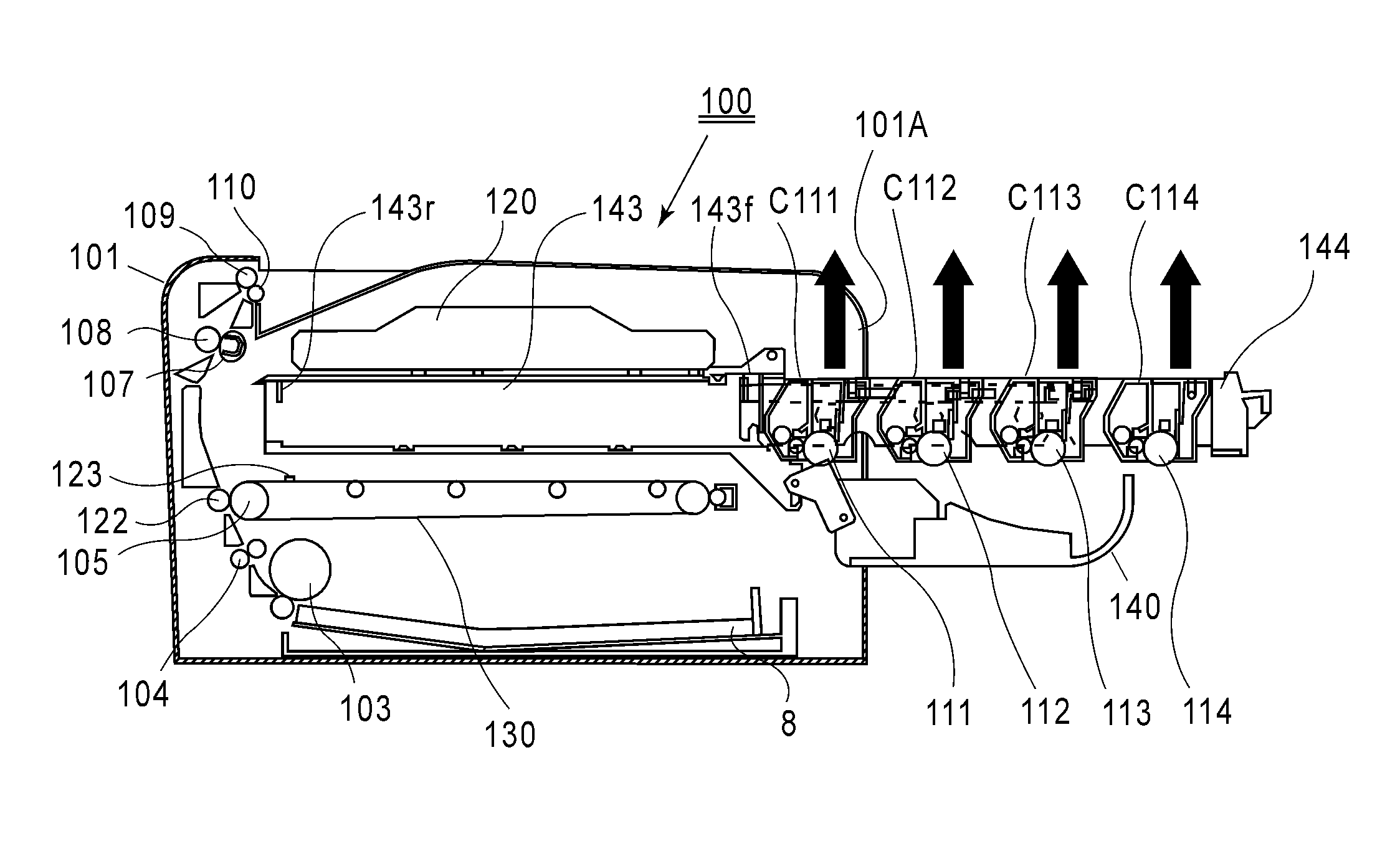
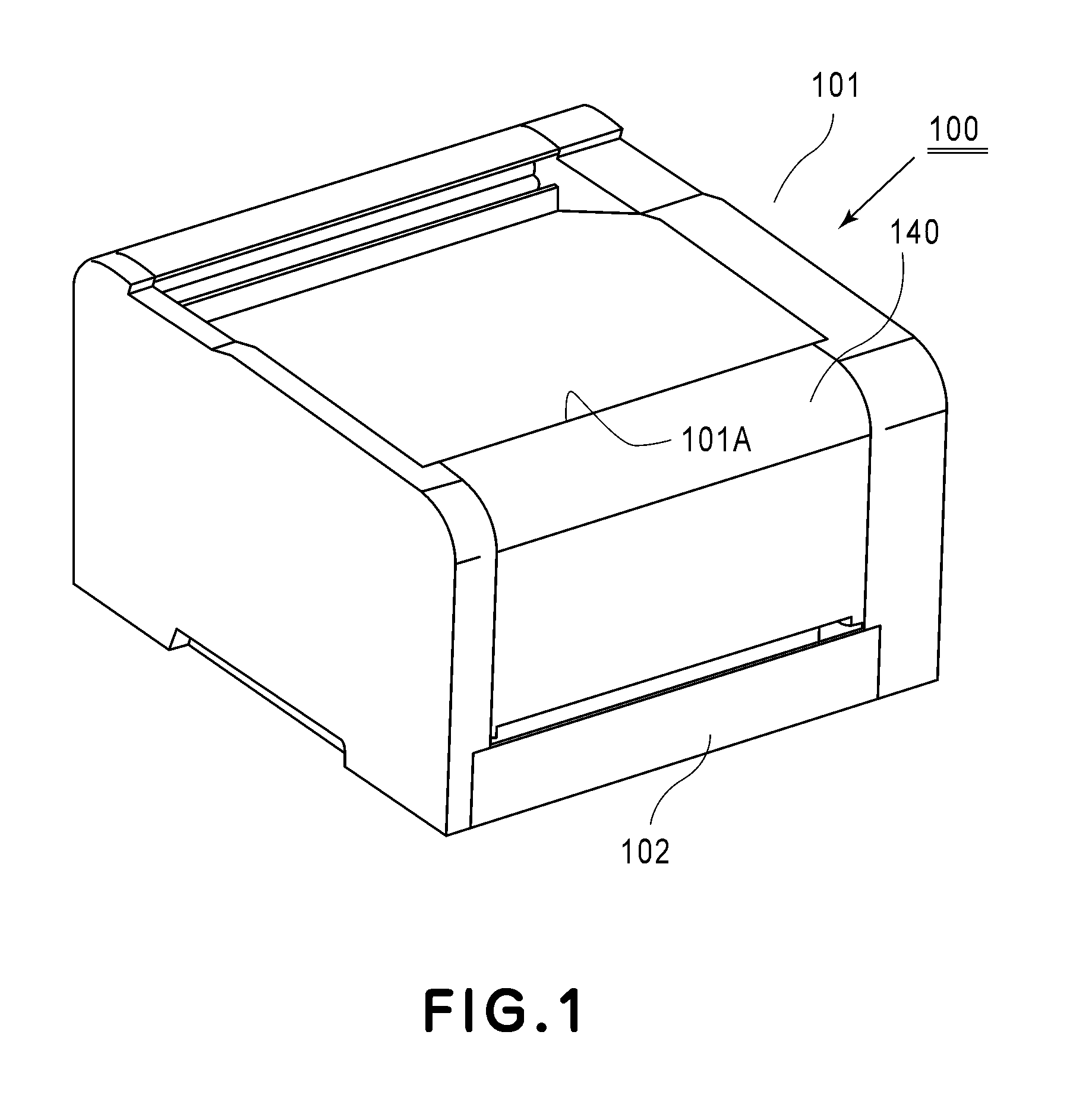
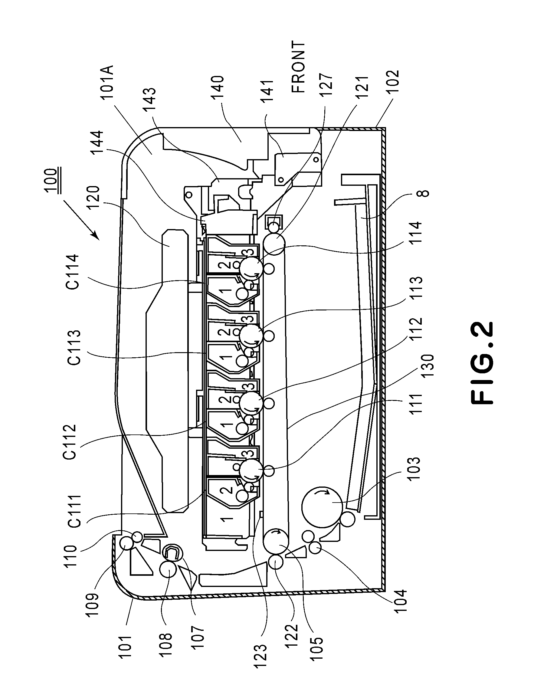
The present invention provides an image forming apparatus capable of improving usability and downsizing the apparatus main assembly while not only shortening FPOT (First Paper Off Time) but also preventing interference between adjacent cartridges. The apparatus includes an opening, an openable member, and a movable member for supporting multiple cartridges. The movable member is designed to move between an inside position where the cartridges are positioned inside the main assembly and an outside position where the cartridges are detachably mountable. When the movable member is moved from the inside position to the outside position, one of the adjacent cartridges is prevented from interfering with the other cartridge by increasing the interval between them. This allows for easy installation and maintenance of the image forming apparatus.

Problems solved by technology

In such cases, it can be difficult to ensure a mounting locus along which an intended process cartridge is detachably mountable in the vertical direction.

Method used


Image

  • Image forming apparatus
  • Image forming apparatus
  • Image forming apparatus

Examples


embodiment 2

[0126]Embodiment 2 of the present invention will be described with reference to FIGS. 13-17. In this embodiment, constituent elements similar to the above-described constituent elements in Embodiment 1 will be omitted from description by adding the same reference numerals or symbols. In this embodiment, a cartridge tray 244 is used.

(Structure of Cartridge Tray)

[0127]FIG. 13 is a perspective view of an outer appearance of the cartridge tray 244 at an outside position. FIG. 14 is a partly enlarged view of the cartridge tray 244 at the outside position. FIG. 15 is a perspective view of an outer appearance of the cartridge tray 244 at the outside position after pulling-out of the cartridge tray 244. FIG. 16 is a perspective view of an outer appearance of the cartridge tray 244 at an image forming position. FIG. 17 is a schematic sectional view of the image forming apparatus at the outside position after the cartridge tray 244 is pulled out.

[0128]The cartridge tray 244 is constituted by ...

embodiment 3

[0142]Embodiment 2 of the present invention will be described with reference to FIGS. 18-21. In this embodiment, constituent elements similar to the above-described constituent elements in Embodiment 1 will be omitted from description by adding the same reference numerals or symbols. In this embodiment, a cartridge tray 344 is used.

(Structure of Cartridge Tray)

[0143]FIG. 18 is a perspective view of an outer appearance of the cartridge tray 344 at an outside position. FIG. 19 is a perspective view of an outer appearance of the cartridge tray 344 at the outside position after pulling-out of the cartridge tray 344. FIG. 20 is a perspective view of an outer appearance of the cartridge tray 344 at an image forming position. FIG. 21 is a schematic sectional view of the image forming apparatus at the outside position after the cartridge tray 344 is pulled out.

[0144]The cartridge tray 344 is constituted by four mounting portions 344(1) and 344(2). The mounting portions 322(1) and 344(2) are...

embodiment 4

[0161]Embodiment 4 of the present invention will be described with reference to FIGS. 22-31. An image forming apparatus 100 in this embodiment is similar to the image forming apparatus 100 in Embodiment 1 but is different from Embodiment 1 in method of increasing the pitch between the drums for mounting and dismounting the cartridges. In this embodiment, constituent elements similar to those in Embodiment 1 will be omitted from description by adding the same reference numerals or symbols. In this embodiment, first to fourth process cartridges C411, C412, C413 and C414, and a cartridge tray 444 are used.

(Mounting and Dismounting Method of Process Cartridge)

[0162]An outline of a process cartridge mounting and dismounting method will be described with reference to FIGS. 22 and 23. FIGS. 22 and 23 are schematic views for illustrating exchange (replacement) of process cartridges, in which FIG. 22 is a perspective view of an outer appearance of the image forming apparatus 100 in a state i...


PUM


Abstract

An image forming apparatus includes: an opening; an openable member; and a movable member, supporting cartridges in a state in which the cartridges are arranged in an arranging direction, movable in the arranging direction while passing through the opening between an inside position and an outside position in a direction crossing the arranging direction and a longitudinal direction. When the movable member is positioned at the inside position, adjacent two cartridges of the cartridges are in an overlapping state as seen in a direction perpendicular to the arranging direction and the longitudinal direction. When the movable member is moved from the inside position to the outside position and then one of the adjacent two cartridges is dismounted from the movable member, the one of the adjacent two cartridges is moved relative to the movable member so as to be prevented from interfering with the other cartridge.

Description

FIELD OF THE INVENTION AND RELATED ART[0001]The present invention relates to an image forming apparatus, in which a plurality of cartridges are detachably mounted in a main assembly thereof, for forming a color image on a recording material (medium).[0002]Here, the image forming apparatus is an apparatus for forming the image on the recording material by using known various image forming principles and types (processes) such as an electrophotographic process, an electrostatic recording process and a magnetic recording process. The image forming apparatus includes, e.g., a copying machine, a printer (a laser (beam) printer, an LED printer, or the like), a facsimile machine, an image display apparatus (electronic blackboard or electronic white board) and the like. On the recording material, the image is formed by the image forming apparatus, and the recording material may include, e.g., a sheet, an OHT sheet, an intermediary transfer member, an image displaying material, and the like....

Claims


Application Information

Patent Timeline
Patent Type & Authority Applications(United States)
IPC IPC(8): G03G15/00G03G21/18
CPCG03G21/1661G03G15/0178G03G21/1623G03G21/1633G03G21/1807G03G21/1853G03G2221/1684
Inventor SATO, MASAKIMATSUOKA, ISAOSASAOKA, OSAMUFURUKAWA, TETSUO
Owner CANON KK
Why Eureka
Eureka Blog
Learn More