Power supply device

a power supply device and power supply technology, applied in the direction of electrochemical generators, electrical apparatus, cell components, etc., can solve the problems of tensile force damage to the thermistor, and achieve the effect of facilitating thermistor insertion work, and saving the space for the thermistor routing area

Inactive Publication Date: 2015-02-26
YAZAKI CORP
View PDF1 Cites 4 Cited by
  • Summary
  • Abstract
  • Description
  • Claims
  • Application Information

AI Technical Summary

Benefits of technology

[0013]However, the thermistor routing area S3 needs to be large because the power supply device 100 has such a configuration that each pair of wire-deformation prevention walls 118 are placed near the thermistor inserting portion 117 to extend in a direction away from the thermistor inserting portion 117, i.e., toward the center of the case body 111 in the width direction W. Further, the wire-deformation prevention walls 118 protruding near the thermistor inserting portion 117 deteriorate operability of inserting the thermistor 122. Furthermore, when a tensile force acts on the thermistor wires W4, the pair of wire-deformation prevention walls 118 can prevent the thermistor wires W4 from bending but cannot prevent the tensile force from acting on the thermistor 122 itself. Such a tensile force may therefore damage the thermistor 122.
[0014]An object of the present invention is to provide a power supply device capable of saving space for the thermistor routing area and improving operability of inserting the thermistor, as well as preventing the thermistor itself from being damaged by the tensile force acting on the thermistor wire.
[0017]According to the above configurations, since the thermistor wire is routed to extend along the thermistor inserting portion, the space for the thermistor routing area can be saved. In addition, since the thermistor wire is fixed to the case body by use of the binding band, it is possible to prevent the thermistor wire from binding without providing any wire-deformation prevention walls unlike in the foregoing related example. Further, since a tensile force on the thermistor wire does not act on a part of the thermistor wire closer to the thermistor than the binding band, it is also possible to prevent the tensile force from acting on the thermistor itself. Furthermore, since no wire-deformation prevention walls need to be provided near the thermistor inserting portion, the thermistor insertion work can be facilitated. In this way, the above configurations make it possible to save the space for the thermistor routing area and improving operability of inserting the thermistor, as well as reliably preventing the thermistor from being damaged by the tensile force acting on the thermistor wire.

Problems solved by technology

Such a tensile force may therefore damage the thermistor 122.

Method used


Image

  • Power supply device
  • Power supply device
  • Power supply device

Examples


Embodiment Construction

[0024]Hereinbelow, an embodiment of the present invention will be descried based on the drawings.

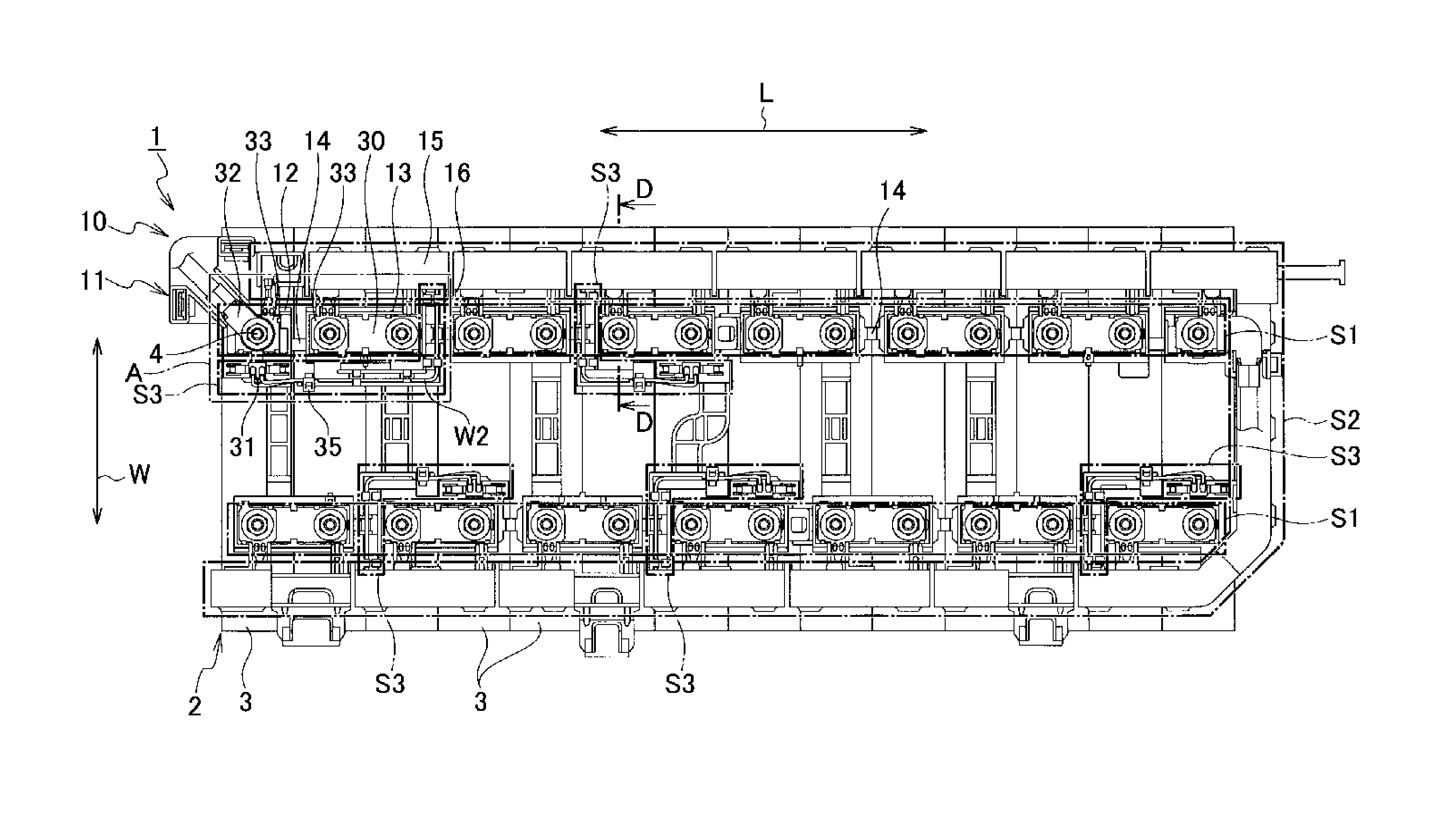
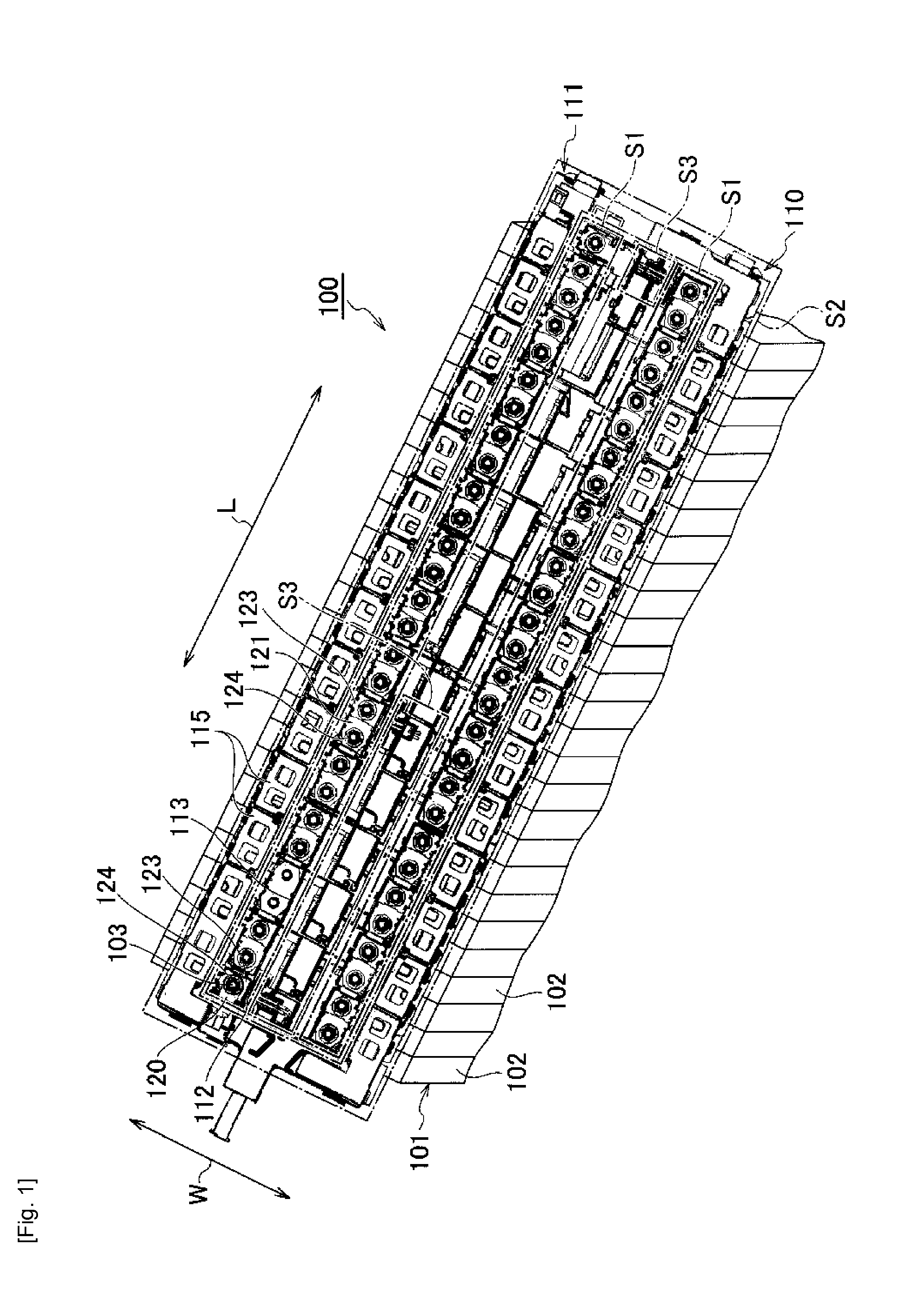
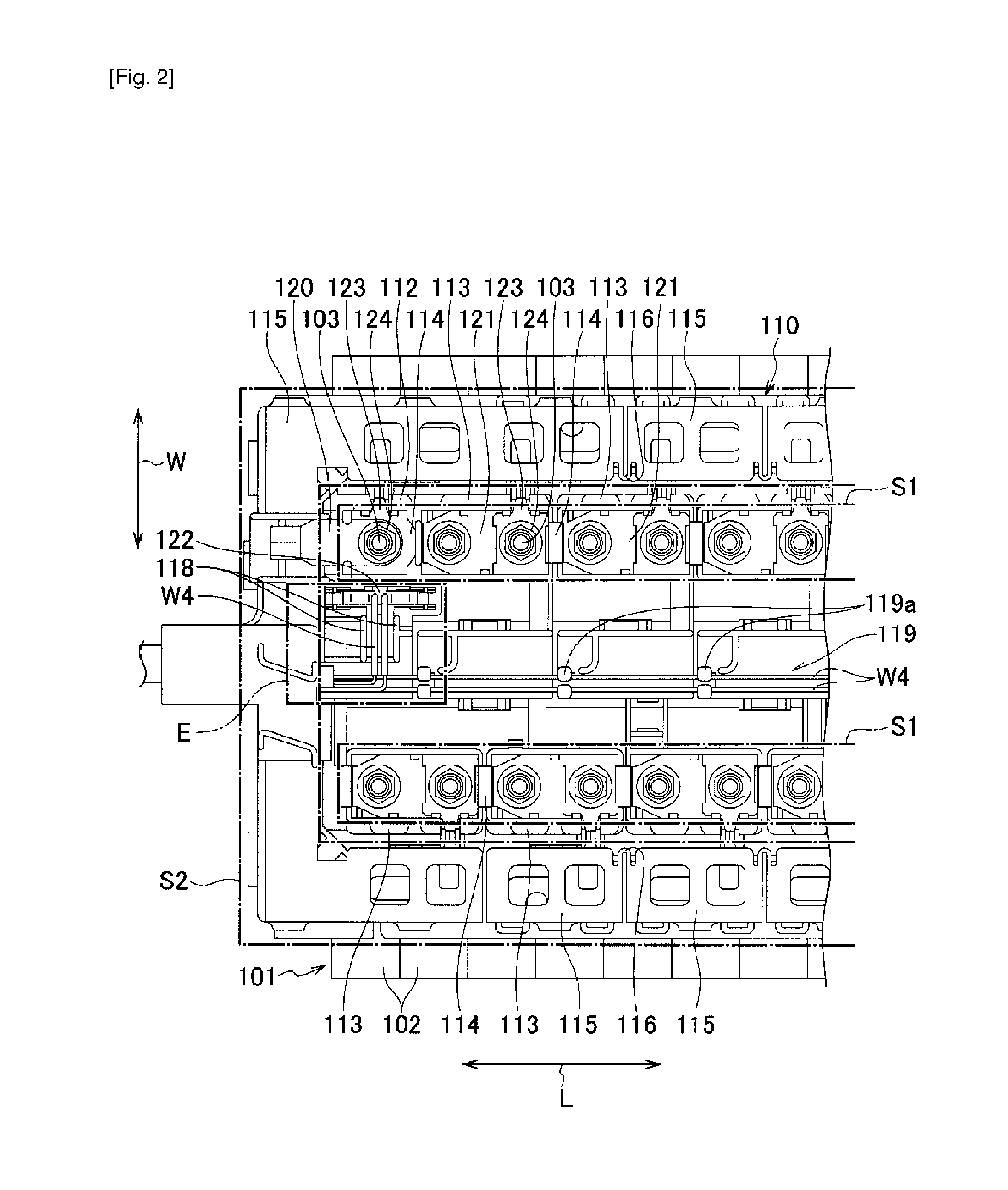
[0025]FIGS. 4 to 6 show the embodiment of the present invention. As shown in FIGS. 4 to 6, a power supply device 1 includes a battery cell assembly 2 and a battery connecting block 10 placed on one side of the battery cell assembly 2 where electrodes of the battery cell assembly 2 protrude.

[0026]The battery cell assembly 2 is an assembly of multiple battery cells 3 stacked in one direction. Each battery cell 3 is provided with a pair of electrodes (positive and negative electrodes) 4 protruding on an upper surface thereof. Each electrode 4 is in the form of a bolt.

[0027]The battery connecting block 10 includes a case body 11 made of an insulating resin, multiple connection terminals 30, multiple thermistors 31, a pair of output terminals 32, and multiple voltage detecting terminals 33. The connection terminals 30, the thermistors 31, the pair of output terminals 32, and the voltage detec...


PUM

PropertyMeasurementUnit
temperatureaaaaaaaaaa
widthaaaaaaaaaa
fixing areaaaaaaaaaaa

Abstract

A power supply device (1) includes a battery cell assembly (2) being an assembly of battery cells (3) each having electrodes (4), a battery connecting block (10) placed on a side of the battery cell assembly (2) where the electrodes (4) are located and including a case body (11) including terminal fixing portions (12, 13) and a thermistor inserting portion (20), terminals (32, 30) fixed to the corresponding terminal fixing portions (12, 13), and a thermistor (31) disposed in the thermistor inserting portion (20) and configured to detect a temperature of the battery cells (3), and a thermistor wire (W2) drawn from the thermistor (31) to extend along the thermistor inserting portion (20) and fixed to the case body (11) by a binding band (35).

Description

TECHNICAL FIELD[0001]The present invention relates to a power supply device in which multiple electrodes of battery cells are connected to one another.BACKGROUND ART[0002]A power supply device serving as a drive source of an electric motor is mounted on a hybrid vehicle or an electric vehicle, for example. Patent Literature 1 discloses a related power supply device of this type. As shown in FIGS. 1 and 2, a power supply device 100 includes a battery cell assembly 101 and a battery connecting block 110 placed on one side of the battery cell assembly 101 where electrodes of the battery cell assembly 101 protrude.[0003]The battery cell assembly 101 has multiple battery cells 102 stacked in one direction. Each battery cell 102 is provided with a pair of electrodes (positive and negative electrodes) 103 protruding on an upper surface thereof. Each electrode 103 is in the form of a bolt.[0004]The battery connecting block 110 includes a case body 111 made of an insulating resin, multiple c...

Claims


Application Information

Patent Timeline
Patent Type & Authority Applications(United States)
IPC IPC(8): H01M10/48H01M50/209H01M50/227H01M50/262H01M50/503H01M50/569
CPCH01M10/486H01M10/482H01M50/227H01M50/262H01M50/503H01M50/569H01M50/209Y02E60/10
Inventor OGASAWARA, SHIGEYUKIYANAGIHARA, SHINICHIOTA, MICHIO
Owner YAZAKI CORP
Why Eureka
Try Eureka