Composite Holographic Optical Diffuser Structure with High Frequency Overlay and Method of Fabrication Thereof

Active Publication Date: 2015-02-26
LUMINIT
View PDF14 Cites 4 Cited by
  • Summary
  • Abstract
  • Description
  • Claims
  • Application Information

AI Technical Summary

Benefits of technology

This patent is about a new way to make optical diffusers that show less visible patterns and can improve the viewing experience of viewers. The technique involves using a combination of microstructure patterns, including smaller ones overlaid on larger ones, to create sharper images and reduce glare and moiré artifacts. This innovation can be useful in applications like movie projection screens and head-up displays, where optical diffursers are commonly used. A high-fidelity replica of the optical diffuser master can also be used for the same benefits in other applications.

Problems solved by technology

As a result, it positively impacts the experience of end users.

Method used


Image

  • Composite Holographic Optical Diffuser Structure with High Frequency Overlay and Method of Fabrication Thereof
  • Composite Holographic Optical Diffuser Structure with High Frequency Overlay and Method of Fabrication Thereof
  • Composite Holographic Optical Diffuser Structure with High Frequency Overlay and Method of Fabrication Thereof

Examples


Embodiment Construction

[0018]The present invention, a composite holographic optical diffuser and method of fabrication thereof, comprises a composite surface relief structure, which acts as a suppressor to visible optical artifacts—in particular, undesirable ones.

[0019]The present invention does this by overlaying smaller (higher spatial frequency) microstructures on top of lower-frequency ones by either of the following:

Method 1

[0020]Performing a first exposure with larger microstructure projections (about 5-100 microns) upon a target substrate coated with photoresist recording media followed by a second exposure with smaller microstructures (about 0.5-3 microns) projected upon the same substrate (i.e., on top of the larger microstructures). The photoresist can be either developed or left undeveloped between these two exposures.

Method 2

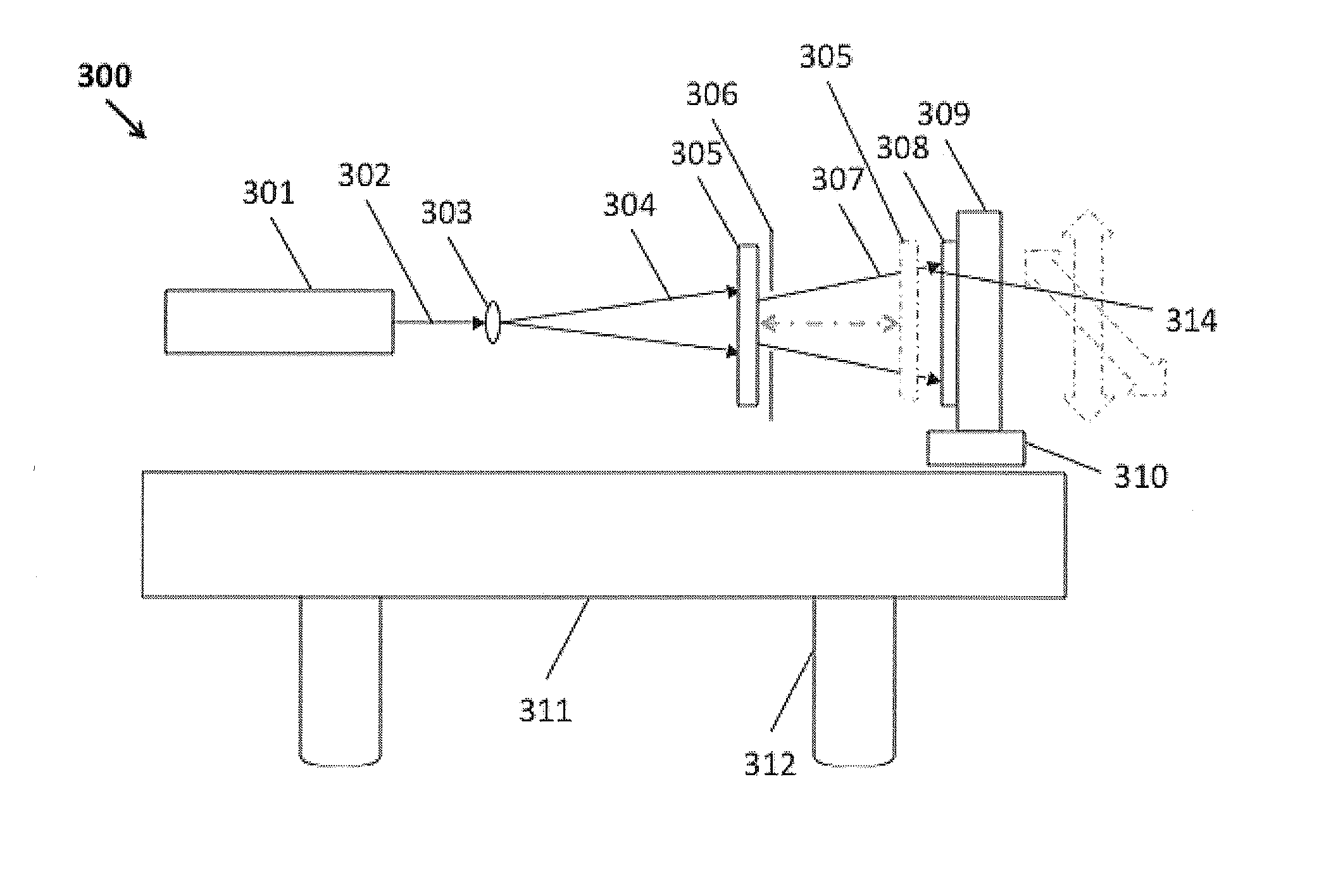
[0021]Placing a partial mirror between the mid-diffuser and the target substrate coated with photoresist recording media, with the partial mirror close (less than 4 inches...


PUM


Abstract

The optical diffuser mastering of the subject invention includes legacy microstructure surface relief patterns, along with smaller ones, overlaid on the larger ones. The characteristic features produced by the present invention will be found useful to eliminate visible structures in / on optical diffusers, such as those used in movie projection screens (utilizing either coherent (i.e., laser-generated) and non-coherent (e.g., lamp-generated) light), head-up displays (HUDs), laser projection viewing, etc., as the present invention produces much sharper images than those afforded by traditional holographic optical diffusers.

Description

FIELD OF THE INVENTION[0001]The present invention is in the field of optics. In particular, it is in the area of optical diffusers.BACKGROUND OF THE INVENTION[0002]The prior art in holographic optical diffusers, which can be found in U.S. Pat. Nos. 6,675,863, 7,700,199, and 8,097,311, all of which are incorporated in their entirety by reference, comprises three-dimensional (3-D) surface relief patterns produced by optically recording laser speckle in thick (10 microns to 60 microns) photoresist material.[0003]Referring to FIG. 1, an optical bench setup 100 capable of recording prior art holographic optical diffuser(s) in planar format, may be used as the starting point for improvements that comprise the present invention.[0004]Referring to FIG. 2, an optical bench setup 200 capable of recording prior art holographic optical diffuser(s) in cylindrical (seamed and seamless) format, may be used as the starting point for improvements that comprise the present invention.SUMMARY OF THE IN...

Claims


Application Information

Patent Timeline
IPC IPC(8): G03F7/20G03H1/04G02B5/32
CPCG03F7/2024G02B5/32G03H2001/0439G03F7/2022G03H1/0402G02B5/0252G02B5/0268G03H1/0244G03H1/202G02B27/48
Inventor ANG, ANTHONYKAO, STANLEY TAFENGLEISTER, CHRISTOPHER
Owner LUMINIT
Why Eureka
Try Eureka