Positioning system for radiotherapy treatment

a positioning system and radiotherapy technology, applied in the field of positioning systems for radiotherapy treatment, can solve the problems of inconvenient operation, complicated process of preparing the patient for radiotherapy treatment (or “set up”), and inability to accurately and reproducibly move, etc., to achieve accurate and reproducible positioning, accurate tracking of movement, and accurate positioning

Active Publication Date: 2015-02-26
ELEKTA AB
View PDF2 Cites 13 Cited by
  • Summary
  • Abstract
  • Description
  • Claims
  • Application Information

AI Technical Summary

Benefits of technology

[0006]Such an arrangement allows accurate and, significantly, reproducibly accurate placement of the optical marker on a patient or any accessory or other equipment. This allows the accurate and reproducible positioning of a patient or any accessory or other equipment relative to the radiotherapy apparatus on initial set up, and also permits the accurate tracking of movement during the radiotherapy treatment by photogrammetry. In addition, the sheet can be provided with identification markings similar to those on the optical markers. This facilitates identification of the correct optical marker for a particular patient, or the appropriate accessory. Accordingly the present invention combines aspects of conventional systems for positioning or identification for radiotherapy treatment, but improves both positioning as well as identification, but reduces the speed of set up, provides improved reproducibility and can be utilised for both a patient and items of equipment or accessories.
[0007]The sheet may be thin, and it may be flexible, for applying to a curved surface, such as a patient's body, or it may be rigid which may be more appropriate in the case of an item of equipment / accessory; it may have an adhesive backing (like the optical marker), so that when it is positioned accurately relative to a patient or other item it can be relied on to stay in position for as long as required. The sheet may be provided with identification markings to enable the sheet to be accurately matched with the identification markings on the optical marker (the markings on the two may be similar); these markings may include barcodes or other markings suitable for being read photogrammetrically, and / or words or symbols easily read by a human operator. In this way, sheets can be matched to the respective optical markers and to the appropriate surfaces to which they are to be affixed / positioned, making set up quicker and easier.
[0008]Additionally or alternatively the markings may include lines, such as two lines; these lines, which may be printed on or formed as grooves in the sheets, may form a cross. This enables the sheets to be easily aligned with the laser (or light) projection on the surface, to act as an indication as to where the optical marker is to be positioned. The crossing of the lines may be within the outline of the upper surface of the sheet, and may be within the hole in the sheet. This facilitates accurate manual positioning of the sheet relative to the surface against which the optical marker is to be positioned, with an operator having to position the hole over the intersecting lines of the projected cross, thus coarsely positioning the sheet, and then accurately positioning it by moving the sheet so that the lines marked on it coincide with the projected lines.

Problems solved by technology

Radiotherapy treatments are often set out in complex treatment plans, requiring the patient to undergo repeated radiotherapy treatments at intervals which can span a considerable time.
This process of preparing the patient for the radiotherapy treatment (or “set up”) is complicated and takes time to carry out correctly, but is absolutely necessary to ensure patient safety and that the radiotherapy treatment is properly and effectively carried out.
Systems employing radiofrequency identification (RFID) tags have been used for identification of the patient and any accessories or other equipments, but these are not yet sufficiently accurate to be used as the sole means of patient positioning (RFID tags are currently accurate to about 1 cm, whereas the radiotherapy treatment requires greater precision, of 1 mm or less).

Method used


Image

  • Positioning system for radiotherapy treatment
  • Positioning system for radiotherapy treatment
  • Positioning system for radiotherapy treatment

Examples


Embodiment Construction

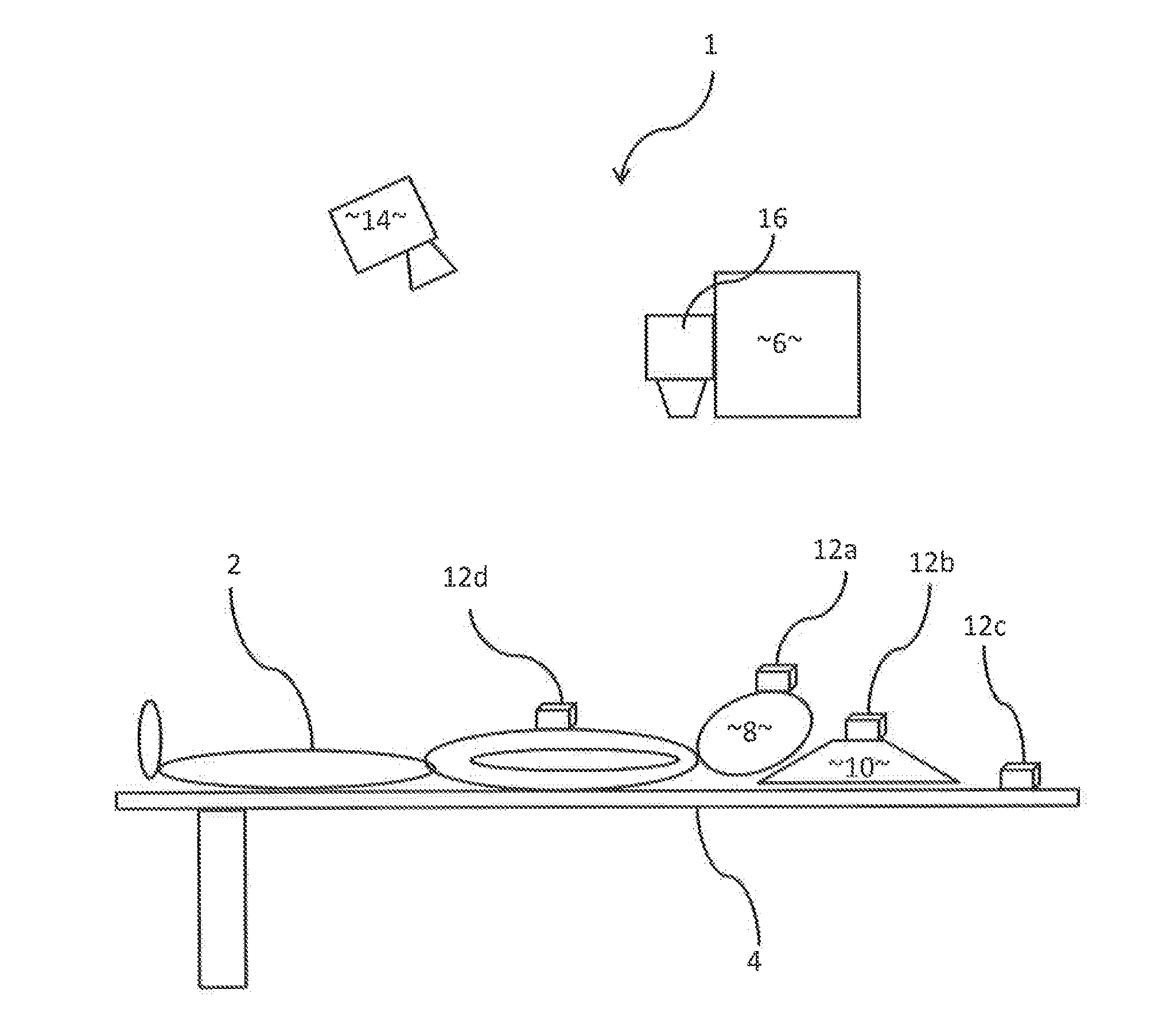
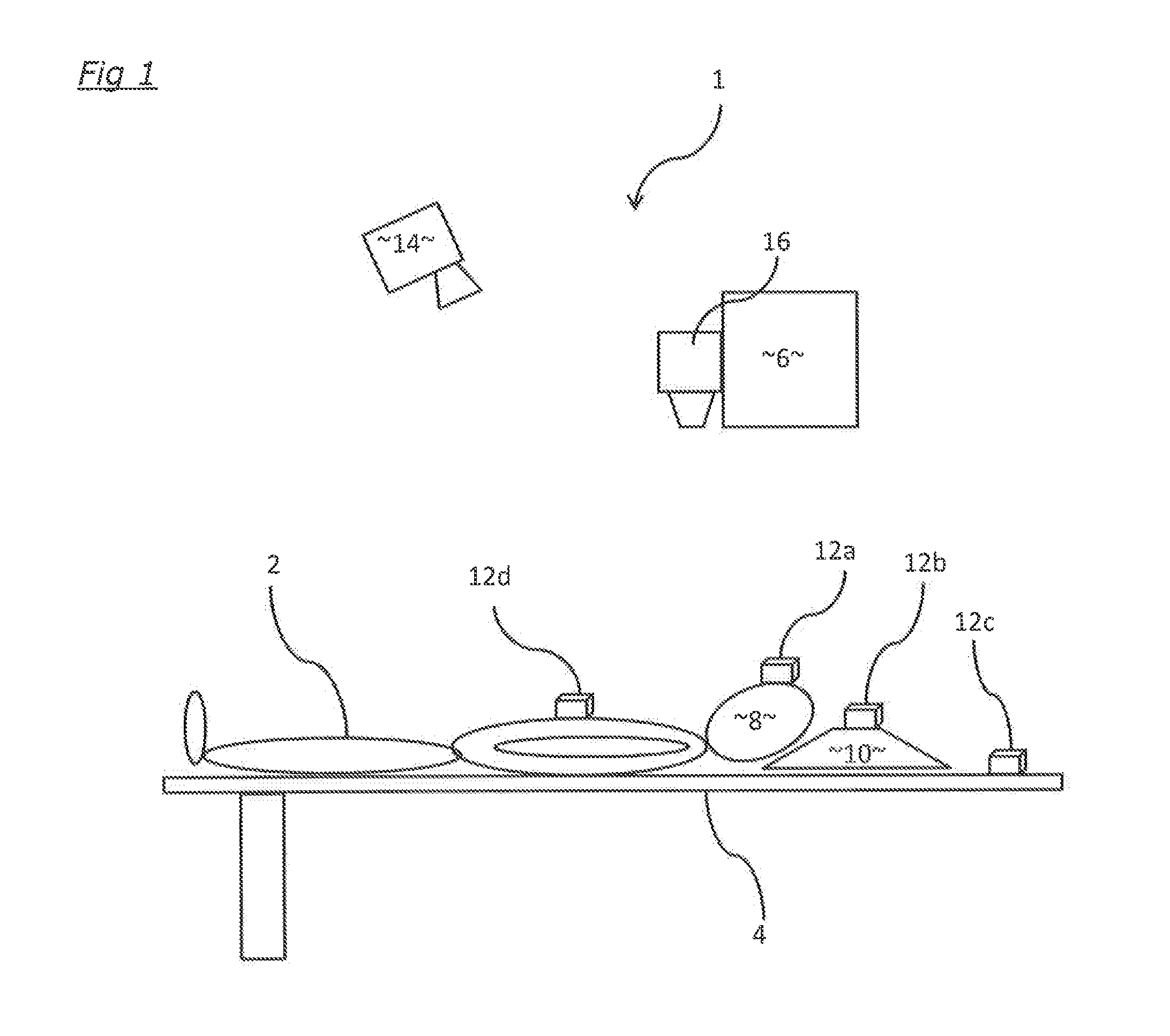
[0015]FIG. 1 shows a radiotherapy treatment system 1 in which a patient 2 is lying on a patient support 4 for radiotherapy treatment generated by a radiation source 6 such as a linear accelerator. The patient support 4 and / or the radiation source 6 are movable so that radiation can be directed at the patient 2 from any desired direction; in this example, the radiation treatment is to be applied to the patient's head 8. The patient's head 8 is supported on a headstep 10. In order for the radiotherapy treatment to be carried out properly as planned, it is important that the patient's head 8 is accurately positioned relative to the patient support 4, which is dependent also on the position of the headstep 10 relative to both the patient support 4 and the patient 2 and / or the patient's head 8. This positioning is monitored photogrammetrically by way of optical markers 12a, 12b and 12c which are fixed to the patient's head 8, the headstep 8 and the patient support 4 respectively; a furth...


PUM


Abstract

An apparatus for placement of an optical marker for radiotherapy onto a surface, wherein the optical marker has a reflective element positioned on a body having an outline and shaped and configured such that the reflective element is in a predetermined position relative to the outline of the body, the apparatus comprising a sheet of material having a hole therethrough which is shaped and configured to conform to the outline of the body and which has an upper surface with markings thereon configured for aligning with an image projected onto the surface on which the optical marker is to be placed.

Description

FIELD OF THE INVENTION[0001]The invention relates to apparatus for the positioning and / or identification of equipment and / or a patient for the purpose of radiotherapy treatment or diagnosis.BACKGROUND ART[0002]Positioning systems are used for the accurate and reproducible positioning of patients and equipment for radiation therapy, diagnostic imaging, surgery and other medical procedures (hereinafter all these are referred to collectively as “radiotherapy treatments”). For modern radiotherapy treatments, precise positioning is imperative; accurate positioning is not only necessary for the patient, but also for accessories, such as supports for the patient or parts of the patient's body (e.g. body bags or cushions, headsteps, neck supports, kneesteps, etc.), or other items of equipment which are employed during radiotherapy. Positioning is normally relative to the room or facility in which the radiotherapy is to take place, in particular relative to the treatment apparatus itself (th...

Claims


Application Information

Patent Timeline
Patent Type & Authority Applications(United States)
IPC IPC(8): A61N5/10A61B19/00
CPCA61N5/1049A61B19/54A61B2019/5491A61B2019/5437A61N2005/1059A61B90/39A61B90/96A61B2090/3937A61N2005/105
Inventor CAREY, PETERBARRY, PAUL
Owner ELEKTA AB
Why Eureka
Try Eureka