Method and device for locating a magnetic object

a magnetic object and method technology, applied in the direction of electrical/magnetic measuring arrangements, instruments, point coordinate measurements, etc., can solve the problem that the removal of the closest magnetometer measurement does not modify, or even enhance, the accuracy of the location, so as to reduce the electrical consumption of the array of magnetometers

Active Publication Date: 2015-02-26
COMMISSARIAT A LENERGIE ATOMIQUE ET AUX ENERGIES ALTERNATIVES
View PDF0 Cites 7 Cited by
  • Summary
  • Abstract
  • Description
  • Claims
  • Application Information

AI Technical Summary

Benefits of technology

[0023]not powering the eliminated magnetometers or reducing the frequency with which measurements are made by th

Problems solved by technology

Furthermore, the applicant has found that eliminating the measurements of the clo

Method used


Image

  • Method and device for locating a magnetic object
  • Method and device for locating a magnetic object
  • Method and device for locating a magnetic object

Examples


Embodiment Construction

[0032]Hereinbelow in this description, the features and functions well known to those skilled in the art are not described in detail.

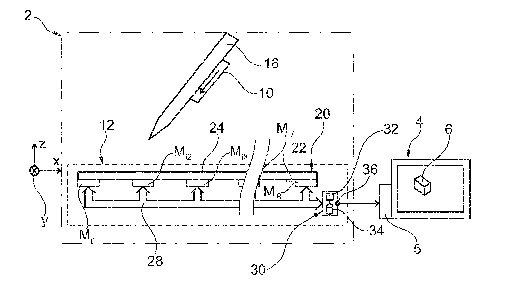
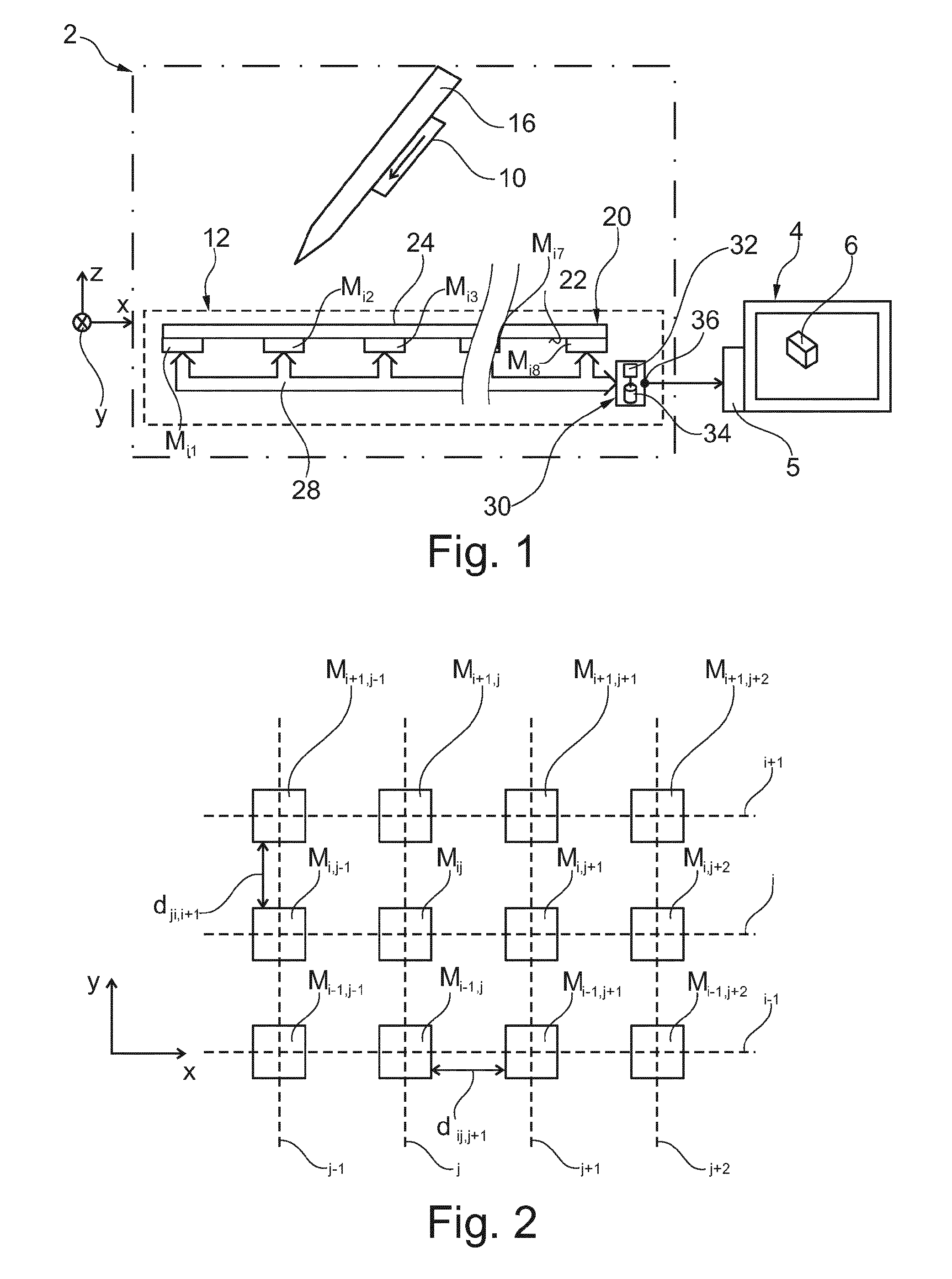
[0033]FIG. 1 represents a human / machine interface 2 making it possible to control an electronic apparatus 4. Here, the apparatus 4 is a screen connected to a control unit 5 capable of controlling the display of an image on this screen 4.

[0034]Here, the operation of the human / machine interface 2 is illustrated in the case where the unit 5 controls the position and the orientation of a cursor 6 on the screen 4. For example, the cursor has a three-dimensional form. In FIG. 1, the cursor 6 is a parallelepiped. However, the interface 2 can be used in numerous other applications as is described at the end of this description.

[0035]The interface 2 comprises a magnetic object 10 and a device 12 for locating this object 10. The object 10 can be freely moved within an orthogonal reference frame XYZ fixed with no degree of freedom to the device 12. Here, the dire...


PUM


Abstract

A method for locating a moving magnetic object, comprising: determining the position or the orientation of the magnetic object from measurements of an array of N (an integer greater than 5) tri-axial magnetometers mechanically linked to one another with no degree, the method also comprises the reiteration of the following steps. Estimating the position of the magnetic object relative to the array of magnetometers from measurements of the magnetometers made in a preceding iteration or from a measurement of a sensor distinct from the magnetometers of the array of magnetometers so that this estimation is obtained before making a new measurement using the magnetometers of the array; computing the distance between each magnetometer and the estimated position of the magnetic object; eliminating the Ni magnetometers closest to this estimated position, where Ni is a positive integer number strictly less than N; making a new measurement, by each non-eliminated magnetometer, of the magnetic field generated or modified by the magnetic object; and determining a new position or a new orientation of the magnetic object from the new measurements of the magnetometers which have not been eliminated and without taking into account new measurements made by the eliminated magnetometers, so as to obtain a new location of the magnetic object.

Description

RELATED APPLICATIONS[0001]This application is a U.S. National Stage of international application number PCT / EP2013 / 056814 filed Mar. 29, 2013, which claims the benefit of the priority date of French Patent Application FR 1252881, filed Mar. 29, 2012, the contents of which are herein incorporated by reference.FIELD OF INVENTION[0002]The invention relates to a method and a device for locating a moving magnetic object. The invention relates also to a screen equipped with such a locating device.BACKGROUND[0003]The known methods for locating a moving magnetic object comprise determining the position or the orientation of the magnetic object from measurements of an array of tri-axial magnetometers, this array comprising N tri-axial magnetometers mechanically linked to one another with no degree of freedom to retain a known distance between each of these magnetometers, where N is an integer number greater than 5.[0004]A tri-axial magnetometer is a magnetometer suitable for measuring the pr...

Claims


Application Information

Patent Timeline
IPC IPC(8): G01B7/004G06F3/046
CPCG06F3/046G01B7/004G01V3/081
Inventor HAUTSON, TRISTANALOUI, SAIFEDDINEDOMINIQUE, DAVIDJOBERT, TIMOTHEEVASSILEV, ANDREA
Owner COMMISSARIAT A LENERGIE ATOMIQUE ET AUX ENERGIES ALTERNATIVES
Why Eureka
Try Eureka