Aerodynamic measurement probe for aircraft

a technology of aerodynamic measurement and probe, which is applied in the field of aerodynamic measurement probe, can solve the problems of affecting the accuracy of the measurement, the inability to measure, and the inability to accurately determine the static temperature of the surrounding air, so as to achieve the effect of limiting its us

Inactive Publication Date: 2015-03-05
THALES SA
View PDF3 Cites 12 Cited by
  • Summary
  • Abstract
  • Description
  • Claims
  • Application Information

AI Technical Summary

Benefits of technology

[0011]The invention aims to propose a novel aerodynamic measurement probe with reduced electrical consumption while retaining the same level of performance. The invention seeks to limit the penetration of particles of ice or of supercooled liquid water in the tube. Thus, it is possible to very significantly reduce the reheating.
[0012]To this end, the subject of the invention is an aerodynamic measurement probe intended to equip an aircraft, the probe comprising a tube intended to face substantially into a flow of air along the aircraft, the tube being open at a first of its ends, a transmitter for emitting an electromagnetic wave directed towards a free zone situated in the extension of the tube on the side of the open end, the electromagnetic wave making it possible to reheat the water likely to be located in the free zone.
[0014]In an advantageous configuration of the invention, the electromagnetic wave is directed towards the free zone by the inside of the tube. This arrangement also makes it possible to reheat the walls of the tube and makes it possible to eliminate any particles of ice (or of supercooled water) that might have penetrated into the tube. The reheating of the walls of the tube makes it possible to dispense with any heating resistor incorporated in the walls of the tube, or at the very least to limit its use. The means for emitting the electromagnetic wave can be positioned inside the tube or outside while retaining a path of the electromagnetic wave via the inside of the tube upstream of the free zone.

Problems solved by technology

On board a fast aircraft, the static temperature of the surrounding air is very difficult, even impossible, to measure.
This temperature sensor would notably be disturbed by the temperature of the outer surface which would risk corrupting the static temperature measurement.

Method used


Image

  • Aerodynamic measurement probe for aircraft
  • Aerodynamic measurement probe for aircraft
  • Aerodynamic measurement probe for aircraft

Examples


Embodiment Construction

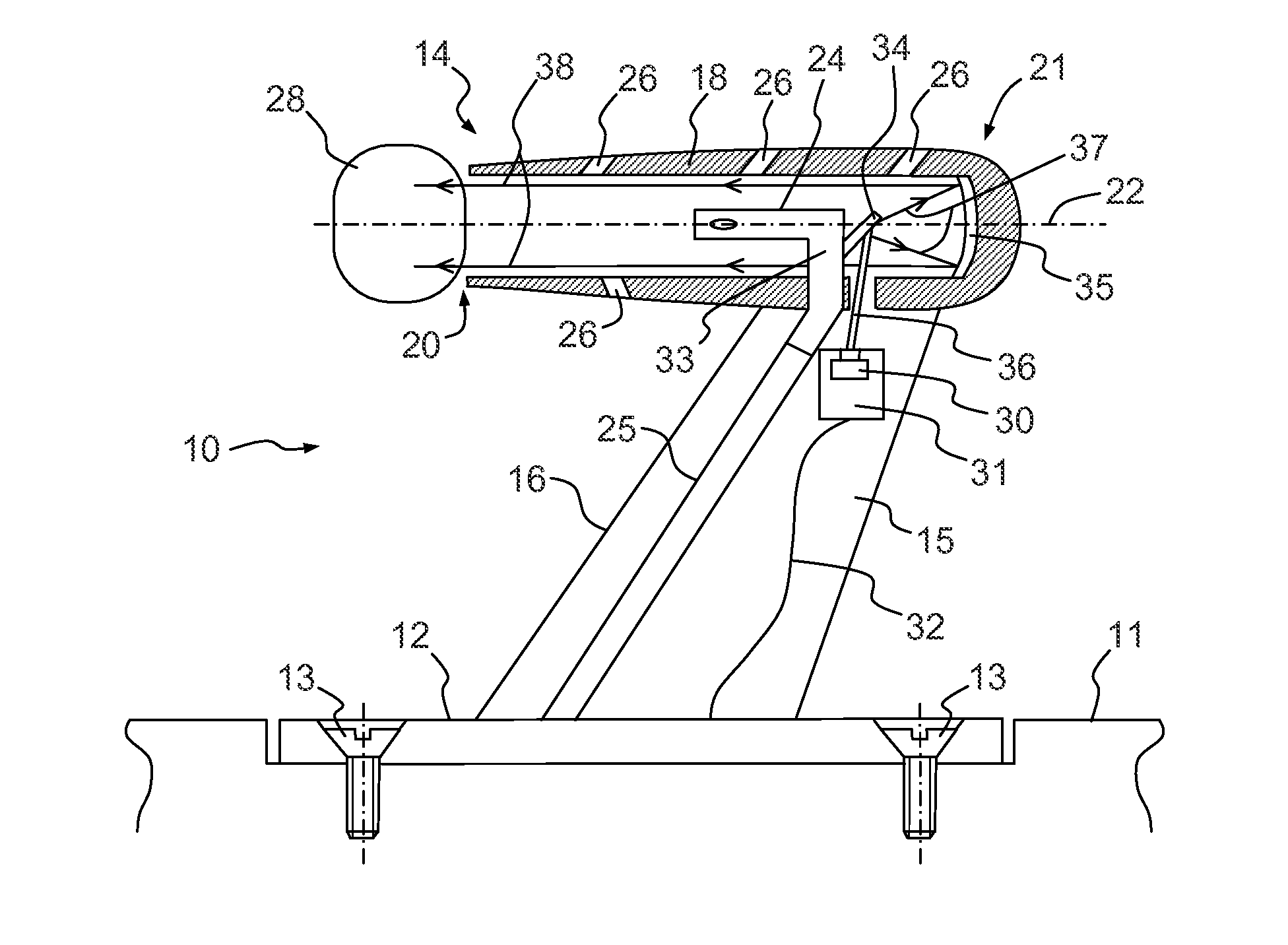
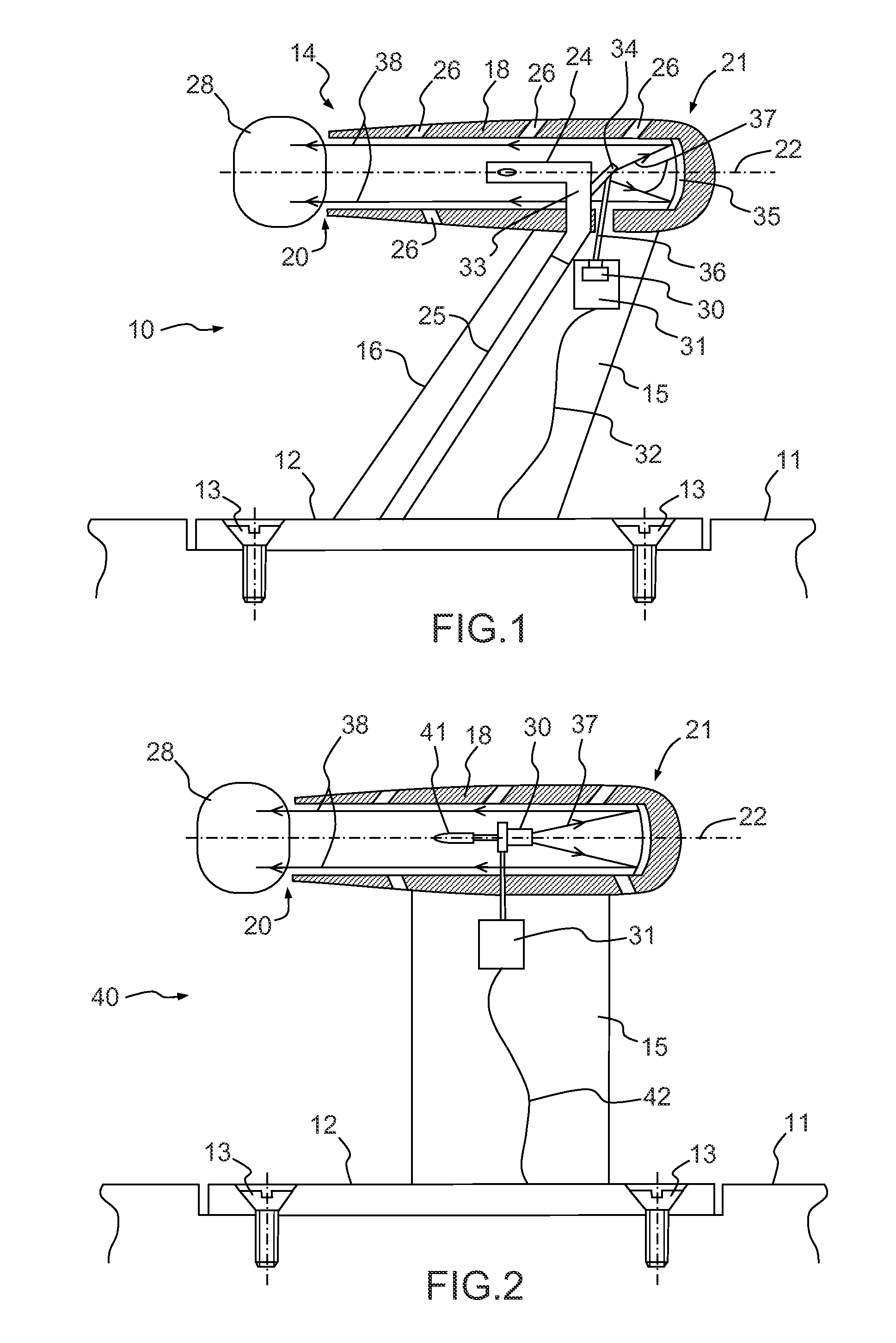
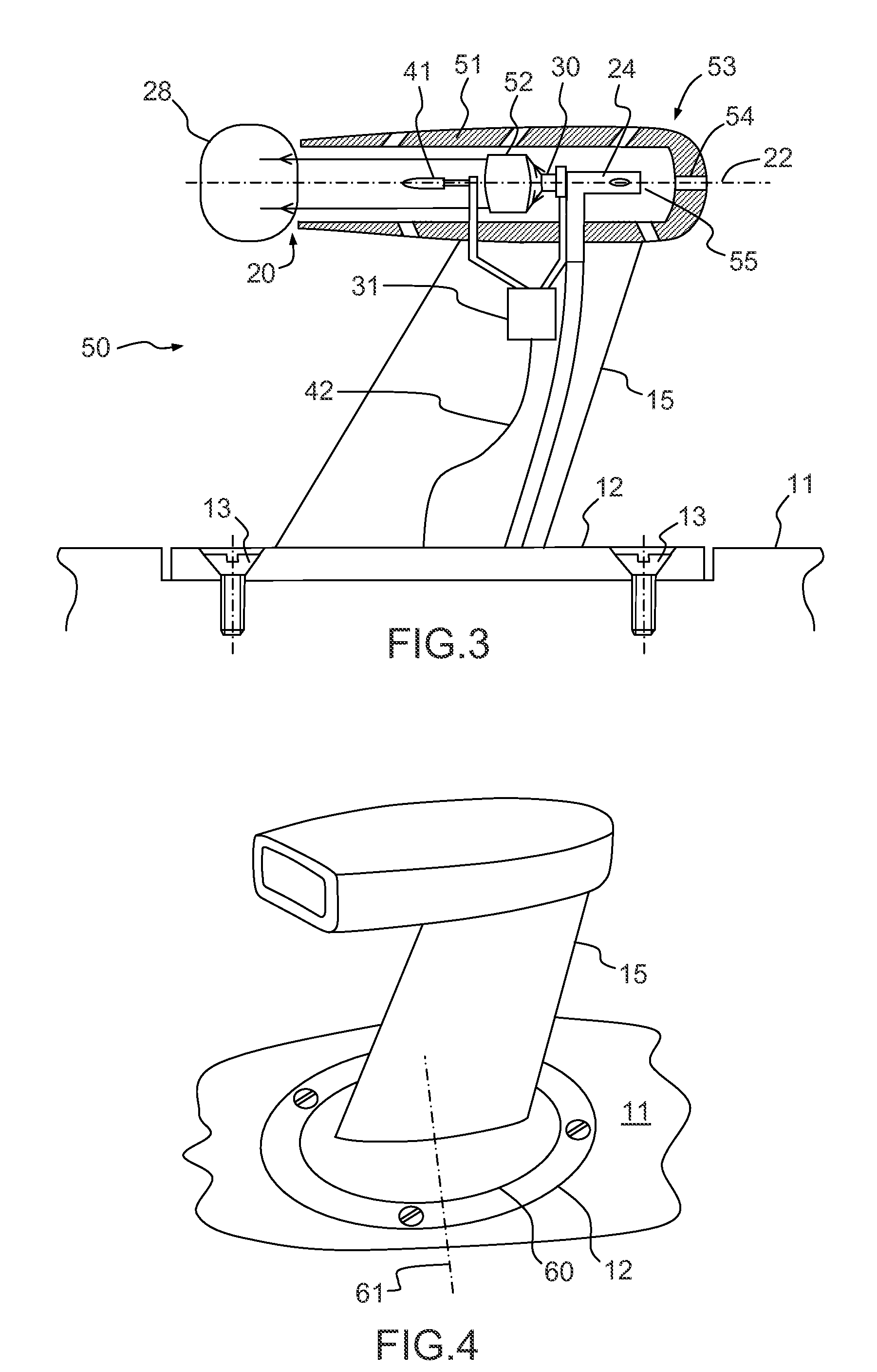
[0022]The probe 10 represented in FIG. 1 makes it possible to measure the total pressure of a flow of air circulating along the outer surface 11 of an aircraft. The probe 10 comprises a base 12 intended to be fixed onto the outer surface 11, for example by means of screws 13. The base 12 is essentially formed by a plate fixed in the extension of the outer surface 11. The probe 10 essentially comprises a Pitot tube 14 secured to a strut 15 linking the Pitot tube 14 to the base 12. Aerodynamic measurement probes are found positioned at different points of an aircraft, such as, for example, at the nose of the aircraft, fixed to its outer surface, often called skin of the aircraft. There are also probes in the air inlet of an engine of the aircraft. The invention can be implemented for any type of probe whatever its position on the outer surface of the aircraft.

[0023]The strut 15 for example has a wing profile having a plane of symmetry, situated in the plane of the figure. The profile ...


PUM


Abstract

An aerodynamic measurement probe intended to equip an aircraft. The probe comprises a tube intended to face substantially into a flow of air along the aircraft, the tube being open at a first of its ends. The probe further emits an electromagnetic wave directed towards a free zone situated in the extension of the tube on the side of the open end, the electromagnetic wave making it possible to reheat the water likely to be located in the free zone.

Description

CROSS-REFERENCE TO RELATED APPLICATION[0001]This application claims priority to foreign French patent application No. FR 1302016, filed on Aug. 30, 2013, the disclosure of which is incorporated by reference in its entirety.FIELD OF THE INVENTION[0002]The invention relates to an aerodynamic measurement probe intended to equip an aircraft.BACKGROUND[0003]Piloting any aircraft entails knowing the modulus of its relative speed, more precisely of its conventional speed relative to the air, that is to say to the relative wind. This speed is determined using probes for measuring the static pressure Ps and the total pressure Pt. Pt−Ps gives the modulus of this conventional speed vector. This aerodynamic parameter makes it possible to determine the modulus of the speed of any aircraft, such as, for example, an aeroplane, a helicopter or an unmanned craft such as a drone.[0004]The measurement of the total pressure Pt is usually done using a so-called Pitot tube. This is a tube that is open at...

Claims


Application Information

Patent Timeline
Patent Type & Authority Applications(United States)
IPC IPC(8): G01P13/02
CPCG01P13/025G01P5/165G01K13/028B64D43/02H05B2214/02H05B6/70H05B6/80
Inventor LEBLOND, HENRIJACQUES MANDLE, JACQUES MANDLE
Owner THALES SA
Why Eureka
Try Eureka