Interlace lifting mechanism

a lifting mechanism and interlace technology, applied in the direction of valve housings, generators/motors, operating means/releasing devices of valves, etc., can solve the problems of inability to move a piezoelectric stack, and inability to control the piezoelectric control valve. application only requires low power,

Active Publication Date: 2015-03-05
HORIBA STEC CO LTD
View PDF5 Cites 27 Cited by
  • Summary
  • Abstract
  • Description
  • Claims
  • Application Information

AI Technical Summary

Benefits of technology

[0006]In consideration of the foregoing, the inventor has invented a mechanism that surrounds a piezoelectric stack actuator and contacts opposite ends of the piezoelectric stack, whereby extension motion (lengthening) of the actuator causes a lifting portion of the mechanism to translate toward the bulk of the actuator while the proximally adjacent mounting portion of the mechanism remains at a fixed location. The mechanism does not contain any gears nor leadscrew threads, and in usual practice is constantly loaded, so apparent change o...

Problems solved by technology

One disadvantage of both magnetic solenoid and thermal expansion type actuators is inherent constant power consumption when controlling valve elements are positioned at an intermediate condition, such as when actively regulating fluid flow.
Consequently, typical piezoelectric control valve applications only require low power and avoid the undesirable generation of heat found in electromagnetic actuators.
A piezoelectric actu...

Method used


Image

  • Interlace lifting mechanism
  • Interlace lifting mechanism
  • Interlace lifting mechanism

Examples


embodiment 100

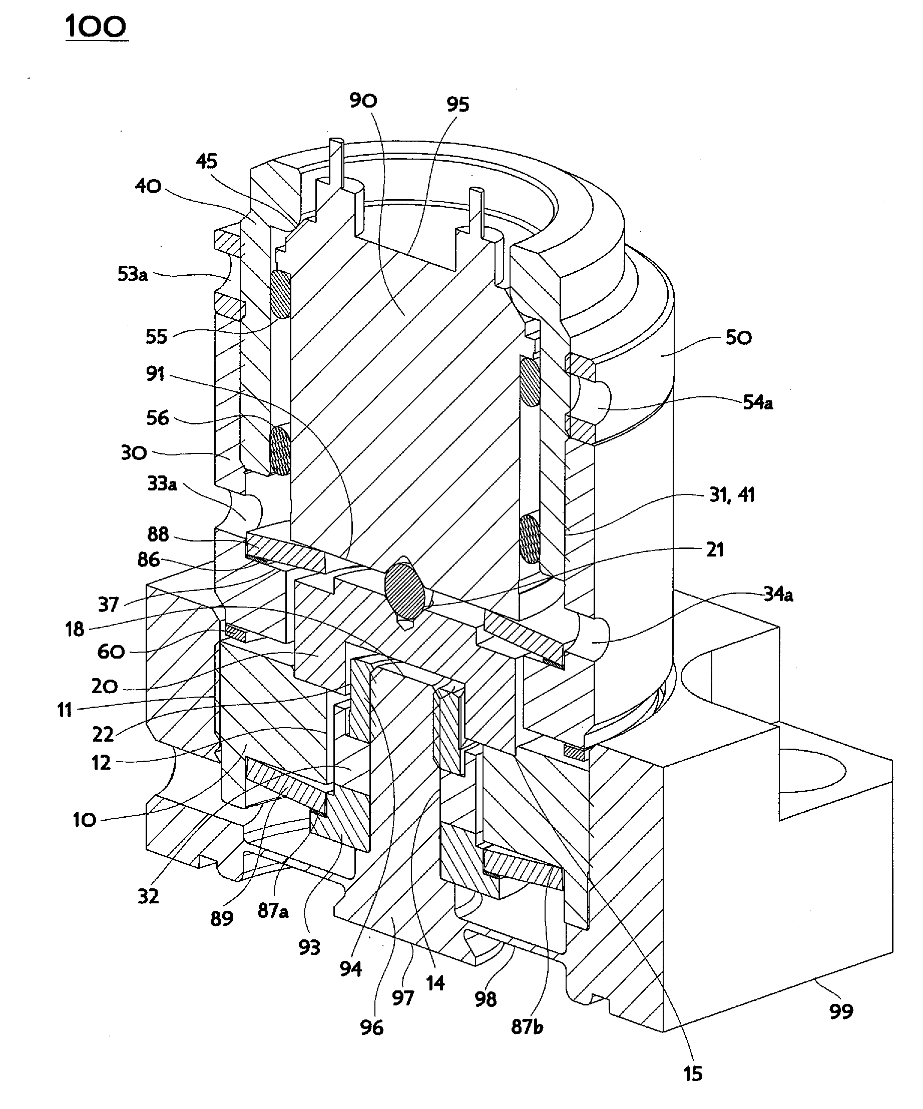
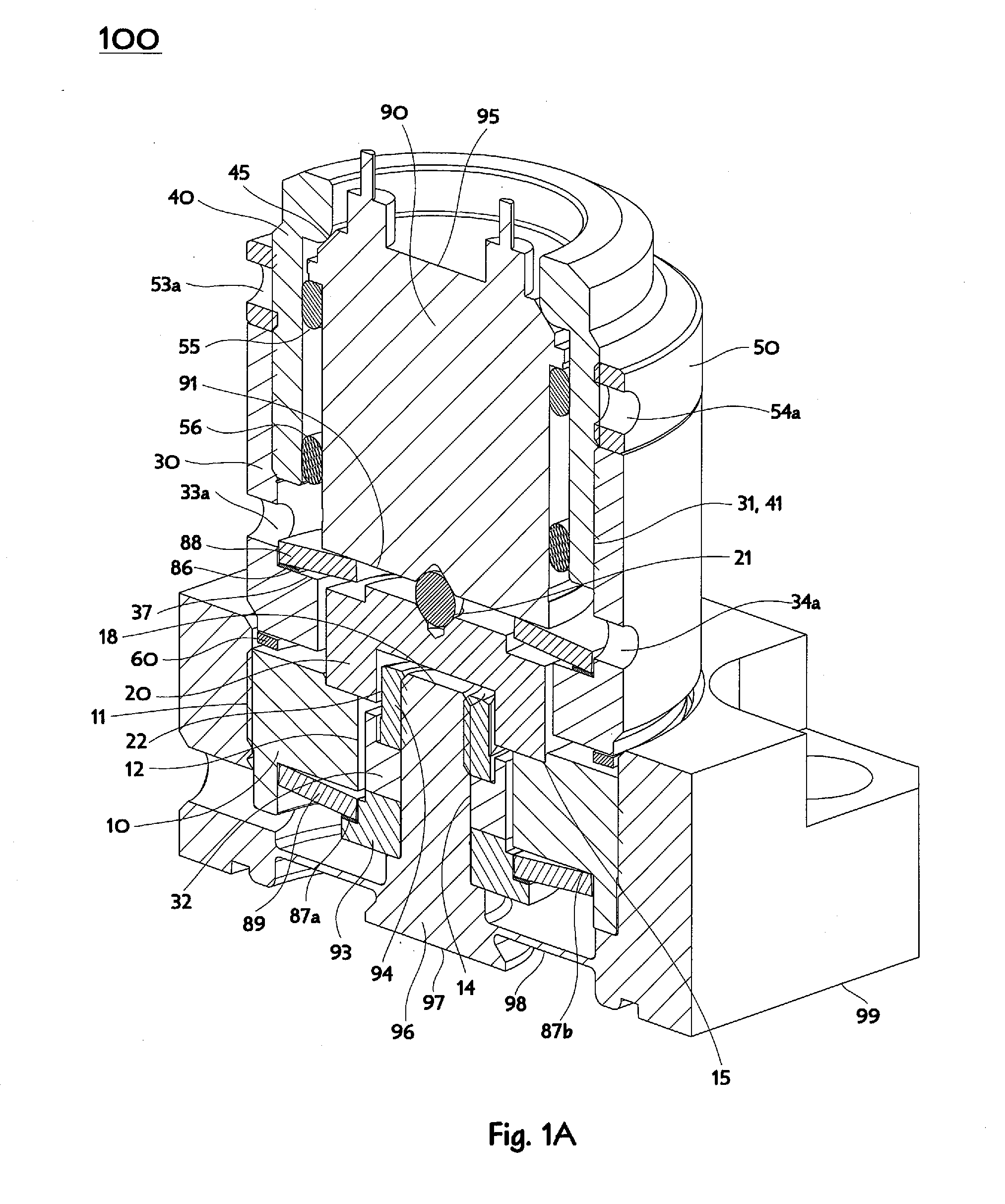
[0046]The mounting nut 10 is pierced axially by an oblong slot 12 and has on its upper surface a step feature 15 beyond the periphery of the oblong slot 12 to receive and locate a cross-over plate 20. The cross-over plate 20 may conveniently be a disk shape with alignment and clearance features on its upper and lower surfaces. FIG. 1A is a cross-section of the representative embodiment 100 of an Interlace Lifting Mechanism, cut perpendicularly to the oblong slot 12, and a traverse bar 32 described further below, thereby showing the cross-over plate 20 sitting atop the mounting nut 10. An alignment feature on the upper surface of the cross over plate 20 may be formed as a conical receptacle 21 and associated spherical bearing (or alternatively a hemispherical tipped load concentration pin) to mate with a suitable conical or similar concavity on a lower end 91 of an actuator 90 to accommodate minor actuator misalignment. A clearance feature on the lower surface of the cross-over plate...

embodiment 500

[0056]The lifting housing 530 is connected to a coupling disc 560 (as illustrated in FIGS. 5A & 5B), and the coupling disc 560 is connected to the mounting nut 510, thereby locating the traverse bar 532 projection within the oblong slot 512. The coupling disc 560 may be formed as a flat ring shape with radially directed diametrically opposite tabs (inwardly directed being more convenient but not limiting for the representative embodiment 500), as illustrated in the example of FIG. 6C and made from a material suitable for use as a spring, such as 17-4PH steel for example, while being compatible with connecting to the lifting housing 530 and connecting to the mounting nut 510. A convenient method of making these connections is by using interference fit pins 671, 672, 673, 674 to connect the lifting housing 530 to the coupling disc 560 and the coupling disc 560 to the mounting nut 510, and is described and illustrated further below in conjunction with FIGS. 6A-6C, FIGS. 7A-7C, and FIGS...


PUM


Abstract

A mechanism for coupling motion of a piezoelectric actuator in axisymmetric devices like modulating proportional valves uses actuator extension motion to cause translation away from a mechanism mounting plane and thereby enables lifting open of a valve element instead of the usual pushing closed of the valve element. The mechanism does not contain any gears nor leadscrew threads, and in usual practice is constantly loaded, so apparent change of direction is achieved without mechanical backlash introducing hysteresis. The mechanism surrounds a piezoelectric stack actuator by contacting opposite ends of the piezoelectric stack, whereby extension motion lengthening the actuator causes a lifting portion of the mechanism to translate toward the bulk of the actuator while the proximally adjacent mounting portion of the mechanism remains at a fixed location.

Description

[0001]This application claims the benefit under 35 U.S.C. 119 of the filing date of Provisional U.S. Application Ser. No. 61 / 959,865, entitled Interlace Lifting Mechanism to Change Actuator from Push to Pull in Proportional Valve, filed on Sep. 4, 2013. This application is also related to U.S. patent application Ser. No. 13 / 794,517 entitled Multiflex Coupling, filed 11 Mar. 2013. Both of the foregoing applications are commonly owned with the present application, and are each expressly incorporated herein by reference, in their entirety.BACKGROUND OF THE INVENTION[0002]The present invention is related to a mechanism for coupling motion of an actuator in axisymmetric devices like modulating proportional valves and is especially useful with regard to piezoelectric actuators. The mechanism uses actuator extension motion to cause translation away from a mechanism mounting plane and thereby enables lifting open of a valve element instead of the usual pushing closed of the valve element. T...

Claims


Application Information

Patent Timeline
IPC IPC(8): F16K31/00
CPCF16K31/007H02N2/043Y10T137/7761Y10T137/7758F16K27/029
Inventor VU, KIM NGOC
Owner HORIBA STEC CO LTD
Why Eureka
Try Eureka