Energy saving apparatus, system and method

a technology of energy saving apparatus and system, applied in the direction of heating types, heating types, instruments, etc., can solve the problem of not intended summary, and achieve the effect of reducing the energy consumption of heating ventilating and air conditioning systems and saving energy

Inactive Publication Date: 2015-03-05
LH THERMOSTAT SYST
View PDF5 Cites 19 Cited by
  • Summary
  • Abstract
  • Description
  • Claims
  • Application Information

AI Technical Summary

Benefits of technology

[0013]In an exemplary embodiment, an energy savings apparatus for reducing the energy consumption of Heating Ventilating and Air Conditioning (HVAC) systems is provided. This is accomplished by extending the fan run time of an HVAC s

Problems solved by technology

Moreover, this Summary is not intended for use as an aid

Method used


Image

  • Energy saving apparatus, system and method
  • Energy saving apparatus, system and method
  • Energy saving apparatus, system and method

Examples


Embodiment Construction

[0019]What follows is a detailed description of the preferred embodiments of the invention in which the invention may be practiced. Reference will be made to the attached drawings, and the information included in the drawings is part of this detailed description. The specific preferred embodiments of the invention, which will be described herein, are presented for exemplification purposes, and not for limitation purposes. It should be understood that structural and / or logical modifications could be made by someone of ordinary skills in the art without departing from the scope of the invention. Therefore, the scope of the invention is defined by the accompanying claims and their equivalents.

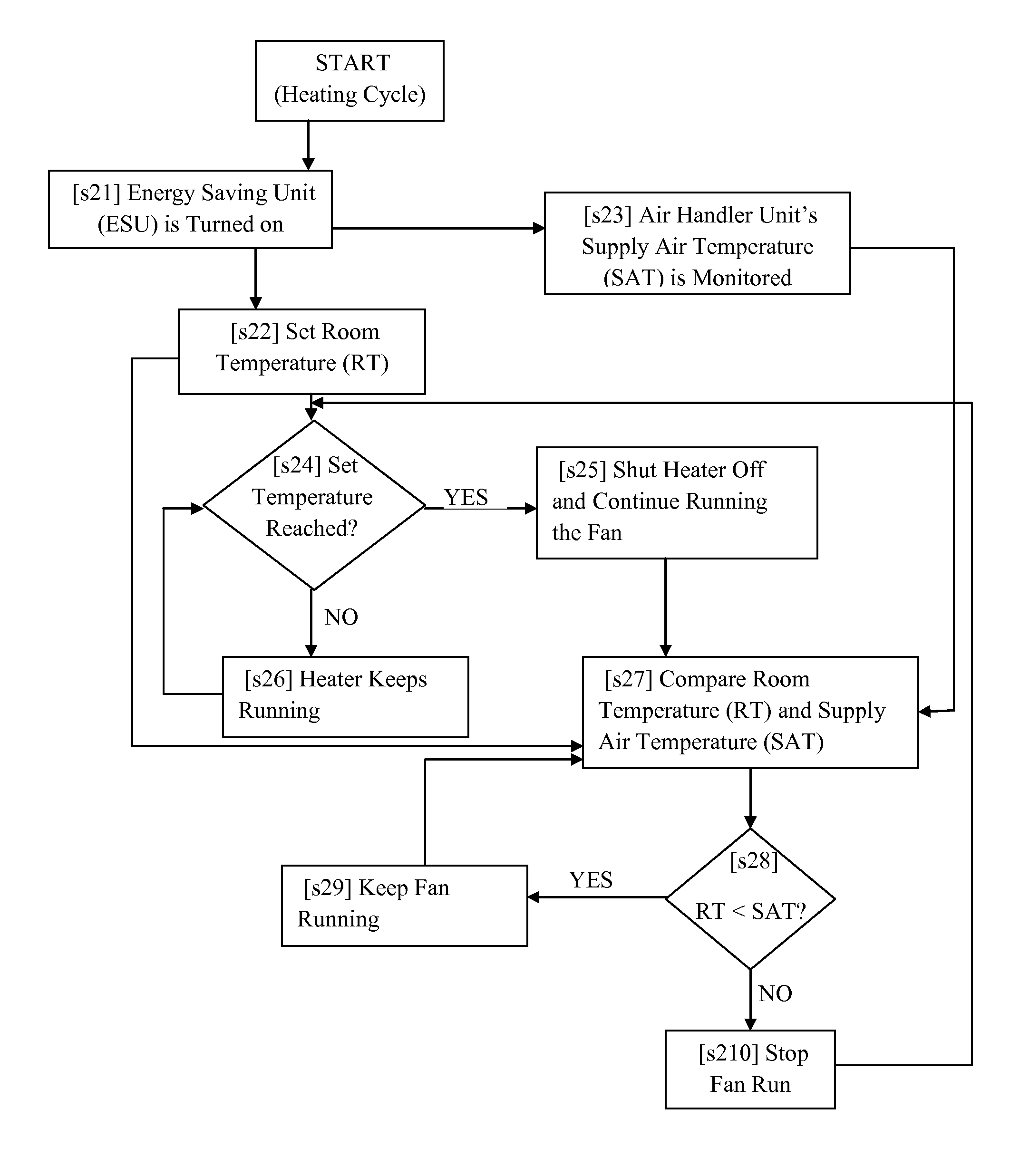
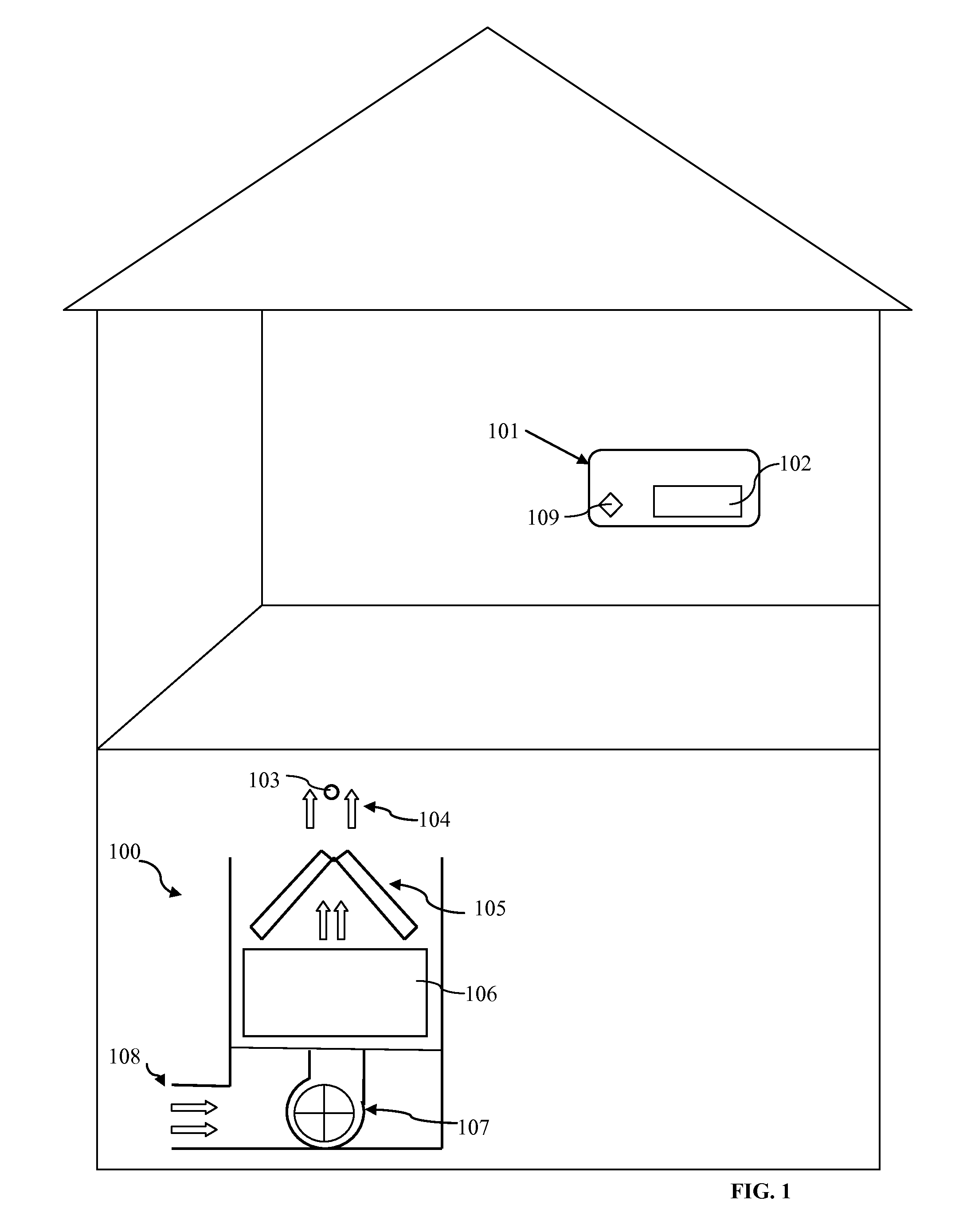
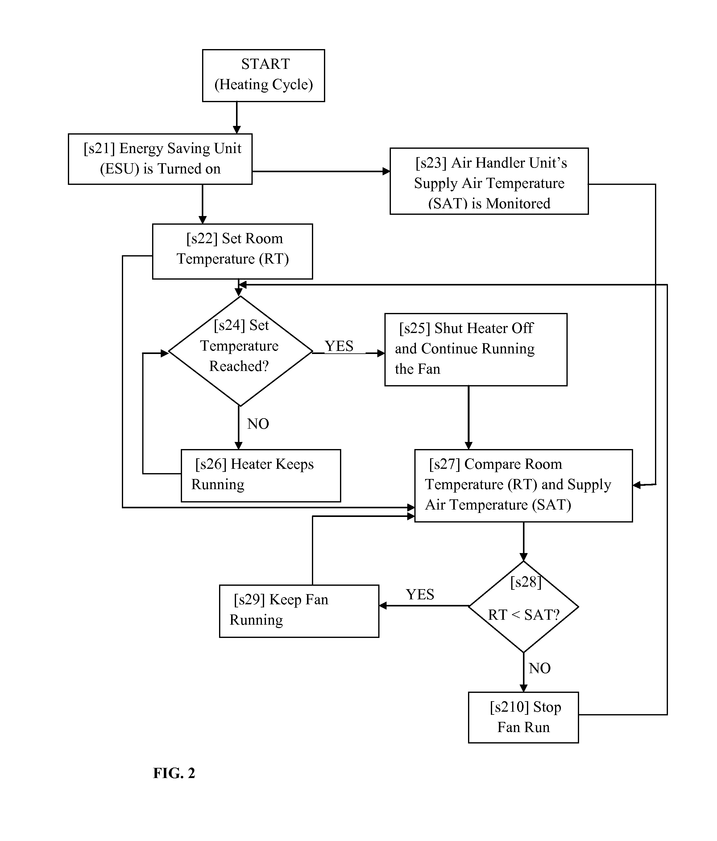
[0020]Reference will now be made to FIG. 1 and FIG. 2. Again, FIG. 1 illustrates a diagram of a system for saving energy during operation of an HVAC, according to an embodiment. FIG. 2 is a flow chart depicting a process for saving energy during the heating cycle of an HVAC, according to an embodi...


PUM


Abstract

A method for energy saving during the operation of an HVAC system comprising an energy saving unit, comprising: installing a temperature probe in the supply air that can send data to the energy saving unit; configuring the energy saving unit to perform a set of functions comprising: receiving a user's instructions for turning on the HVAC system and setting a target room temperature; shutting off the heater or compressor when the target temperature is reached; measuring the temperature of the air in the room that is being heated or cooled and comparing the temperature of the supply air with the temperature of the air in the room; and causing the blower to keep running after shutting off the heater or compressor for as long as the temperature of the air in the room is smaller or greater than the temperature of the supply air, respectively.

Description

CROSS-REFERENCE TO RELATED APPLICATIONS[0001]This application claims the benefit of U.S. Provisional Application No. 61 / 980,537, filed Apr. 16, 2014, and is a continuation-in-part of application Ser. No. 14 / 016,012 filed Aug. 30, 2013, which are hereby incorporated by reference, to the extent that they are not conflicting with the present application.BACKGROUND OF THE INVENTION[0002]1. Field of the Invention[0003]The invention relates generally to Heating Ventilating and Air Conditioning (HVAC) systems, and more particularly to an apparatus, system and method for saving energy during use of HVAC systems, by manipulating the HVAC systems' fan run time and / or compressor run time.[0004]2. Description of the Related Art[0005]Conventional HVAC systems include temperature changing components for changing the temperature and condition of air. Indoor air handler unit drives air from the temperature changing component through supply ducts to zones within a building. A typical HVAC consists o...

Claims


Application Information

Patent Timeline
IPC IPC(8): F24F11/00F24D19/10F24F11/04
CPCF24F11/0012F24F11/0008F24F11/0015F24F11/0076F24F11/04F24D19/1087F24F11/053G05D23/1931F24D5/04F24D5/12F24D19/1084F24F11/30F24F2110/10F24F2110/20F24F11/70F24F11/74F24F11/76Y02B30/13F24F11/46F24F11/63F24F11/86
Inventor LAU, JAMES LEYCH
Owner LH THERMOSTAT SYST
Why Eureka
Try Eureka